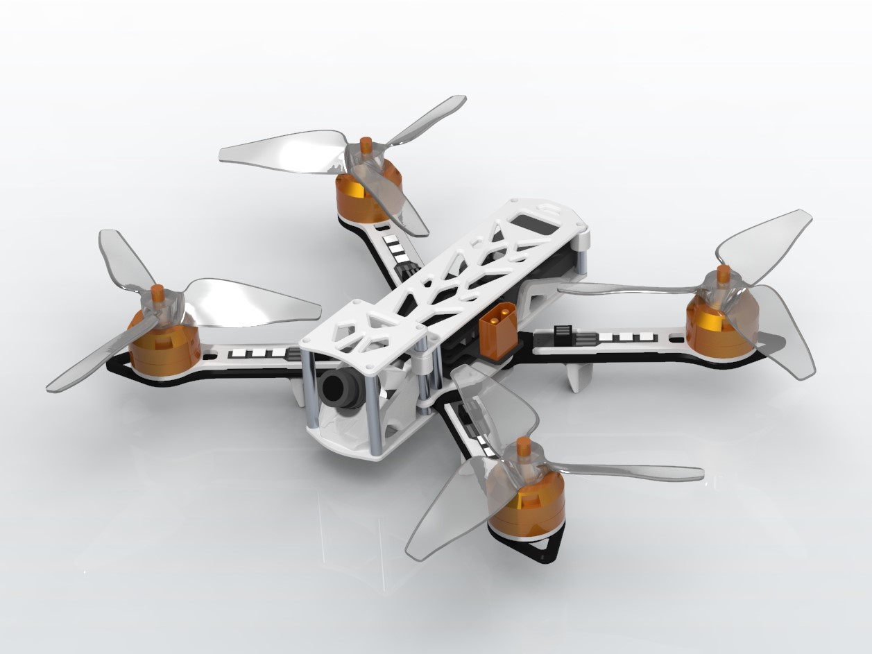
3D Printed FPV Quadcopter
Ever get access to a new tool or machine and wish to use it for everything? Well that was the situation I found myself in when I got my 3d printer. I wanted to build something that flies, but I’ve never designed anything like an RC plane or quadcopter before. I found a nice tutorial online for electronics, but I was going to be all on my own for mechanical design. Since quadcopters are significantly simpler than helicopters in terms of mechanical design, I decided to dip my toes into the world of FPV (first-person-view) quadcopter building and flying.
Most people have the common misconception that flying quadcopters can be expensive and dangerous. However, for the cost, it wasn’t much because I made the gamble of trusting a sketchy chinese website to ship over some electronics by sea. As for safety, I just had to trust in my soldering abilities and try to remember safe lipo-battery protocol to make sure nothing catches fire or explodes or hurts anyone. Strapping a high power density battery to a flying bundle of hand soldered wires and questionable electronics with sharp blades spinning millimeters away at a couple thousand rpm…ahhhh the smell of safety.
As ironic as I may have sounded, I did in fact try to design this to be as safe and practical as possible. Now for the build!
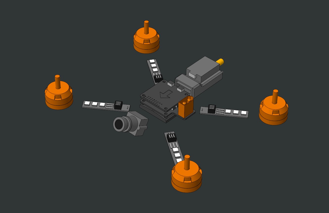
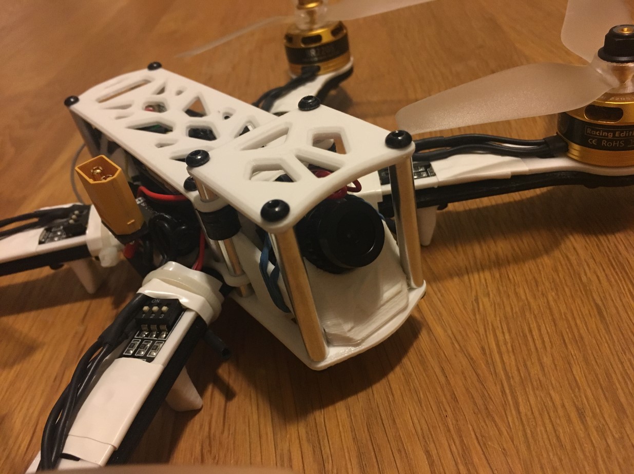
After waiting for what seemed like my entire summer break, my electronics from China arrived in a very suspicious bundle of bubble wrap, styrofoam and shipping tape. It was like the cardboard box got lost in shipping or something. Anyways, with the parts in hand I made some simple representations in cad and laid everything out. Conveniently the flight controller board, power distribution board and esc board could be screwed together into a sort electronics sandwich. Sandwiches are important, so the main electronics boards were placed in the center of the quadcopter farthest away from the propellers. The remote control receiver and video transmitter modules also fit neatly together. I placed the communication modules in the rear of the frame, so that the antenna could stick out the back and not interfere with any other components or moving parts. The fpv camera obviously needs to point out the front with a slight angle. The motors just need to be far enough apart that the propellers have enough clearance to the other components. Led sticks are placed on each arm to signal direction when piloting without fpv goggles. With all of the parts laid out, I could start designing the frame to be 3d printed.
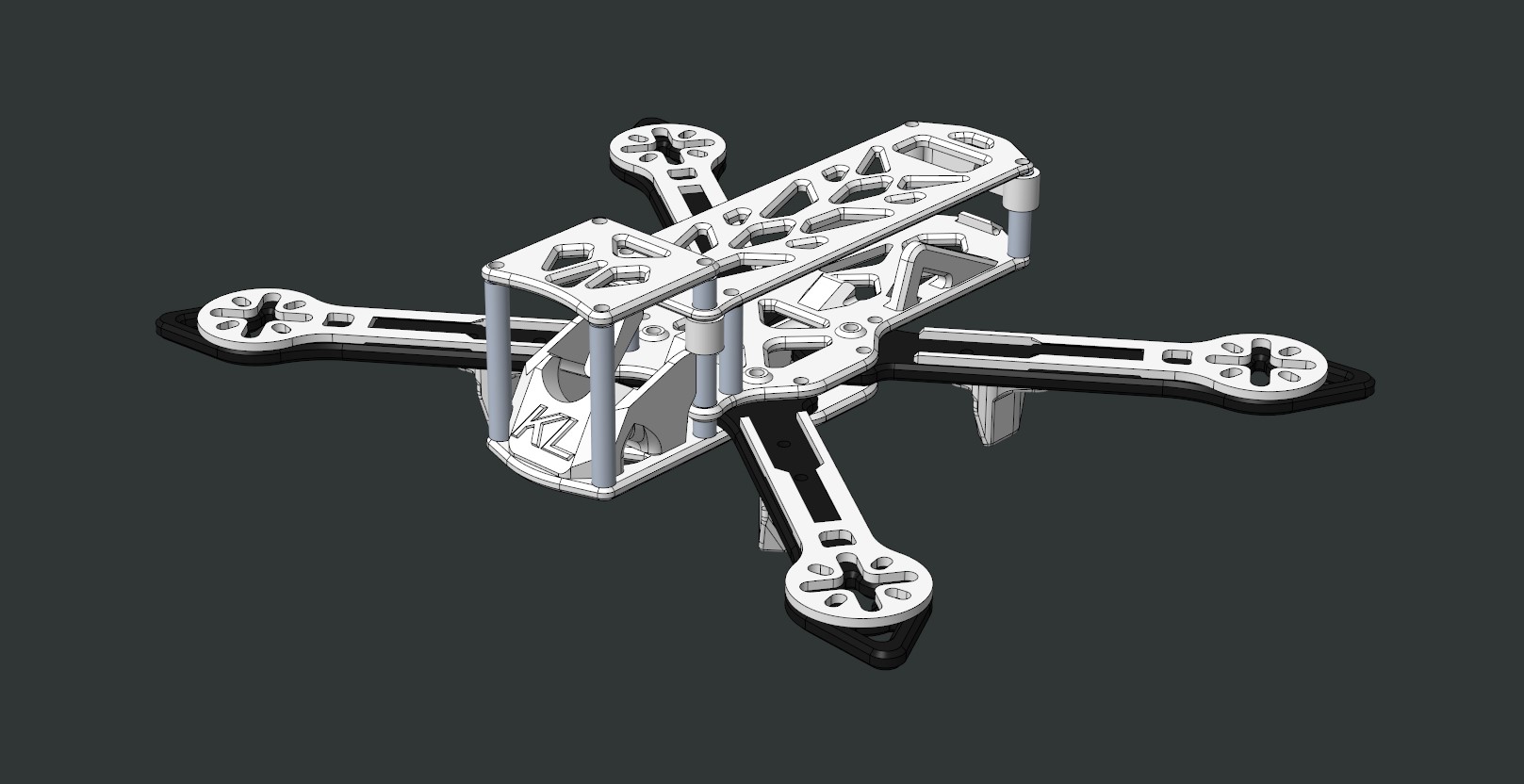
I decided to go with a modular hybrid-x frame shape design. Most fpv quadcopter frames are made of lightweight and strong, but expensive carbon fiber. I did not want to get a carbon fiber frame that would cost more than all my electronics combined, so I had to design around the disadvantages of 3d printed pla plastic. Unfortunately my 3d printer is unable to print stronger abs material, so I was stuck with pla. Since pla is much less stiff than carbon fiber, I had to thicken all of the plates to get close to the overall frame stiffness. Pla is also much less impact resistant than carbon fiber, so I had to design with the intention of making it easy to replace any broken plates.
Crashing while learning how to pilot an fpv quadcopter is practically inevitable. I determined that the most likely part to break are the arms, since they will experience the most force from the impact of crashing. Hence the modularity designed into the frame makes it possible to swap the arms out in the event of a crash without taking apart the entire quadcopter. I think that the slight increase in weight from the modular hardware is worth it for saving time on repairs. With the frame nearly complete, the last step is to determine cable routes and place cable tie down points. Cable routing and tie down points are extremely important since fast spinning blades are literally millimeters away from some cables.

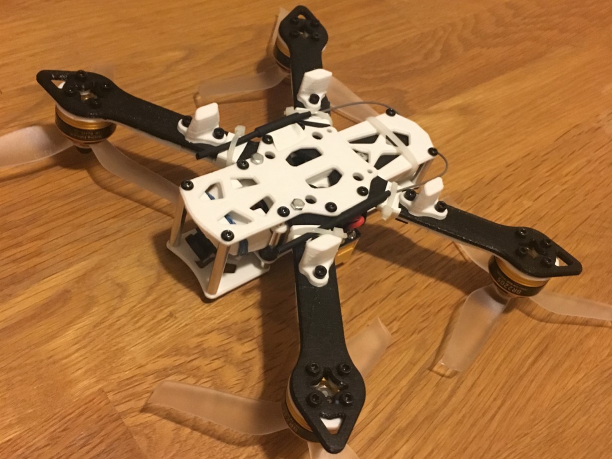
After my first crash into a tree about a couple minutes into flying, the arm broke exactly where I had thought the point of failure would be. One of my propeller blades was bent, so I determined that the front left propeller hit the tree transmitting the force through the motor to the arm, breaking it. Luckily it was simple enough to print another arm and replace it. I also had spare propellers, so the fix was quick and painless. Unfortunately the fpv transmitter antenna snapped off the module possibly from when the quadcopter made contact with the ground and I was unable to use the fpv feature for a while.
In the end I was able to design and build my first controllable flying object. I learned how to use a soldering iron for the first time and how to set up a flight controller. A future upgraded design would have a stiffer frame geometry for more precise control, an adjustable angle fpv camera mount, a hot swappable battery slot, and possibly a gopro mount.
Skills Enhanced
- CAD (PTC Creo Paramtric)
- 3D Printing