2018 Summer F4 CADathon
This is my submission to the 5th Bi-annual CADathon hosted by F4. My robot was designed to FIRST Robotics Competition (FRC) rules and specifications to play in a virtual competition. Teams made of one to three designers from around the world were given 72 hours to plan, design, render and document a full FRC class robot. I decided to enter the competition as a solo team to see what my capabilities were. This was also the first FRC class robot I designed totally on my own .
This year’s design challenge was called “Connect F4”. Teams had to design robots to play in a virtual game of Connect Four with a huge 9-foot tall Connect Four board and 14 inch wide discs. Two alliances with three robots each would go against each other to score the most points. Points could be received by depositing discs into the Connect Four board and extra points would be received for Connect Four combos. Now since this was a CADathon and no one was required to physically build the robot, the robot designs were judged by a panel of professional engineers, mentors and alumni. Each team’s robot submissions were judged with several criteria including strategy, appearance, manufacturability, and perceived challenge efficiency. My design’s strategy focused on having multiple disc intake positions and quick alignment with the scoring board.
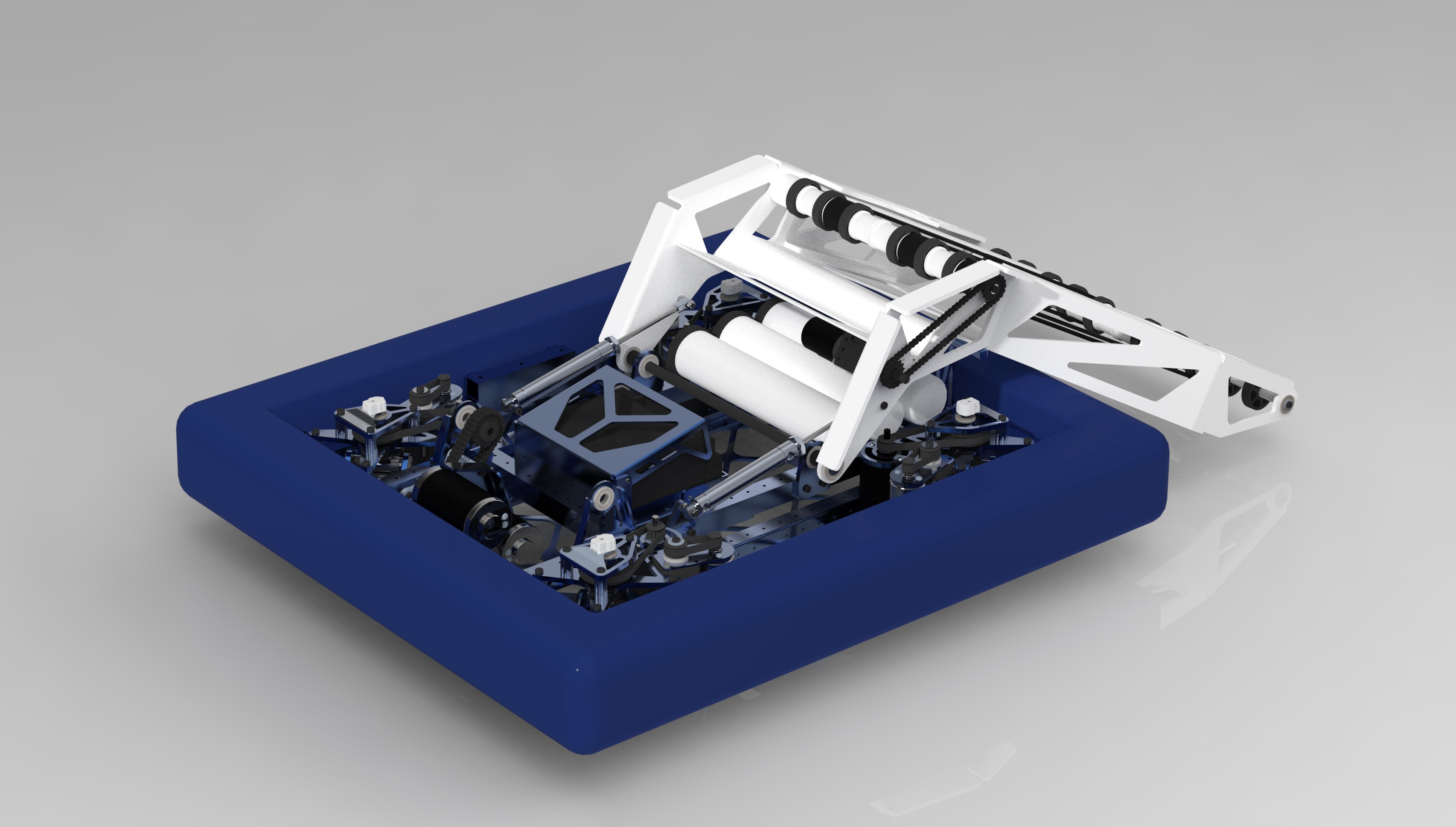
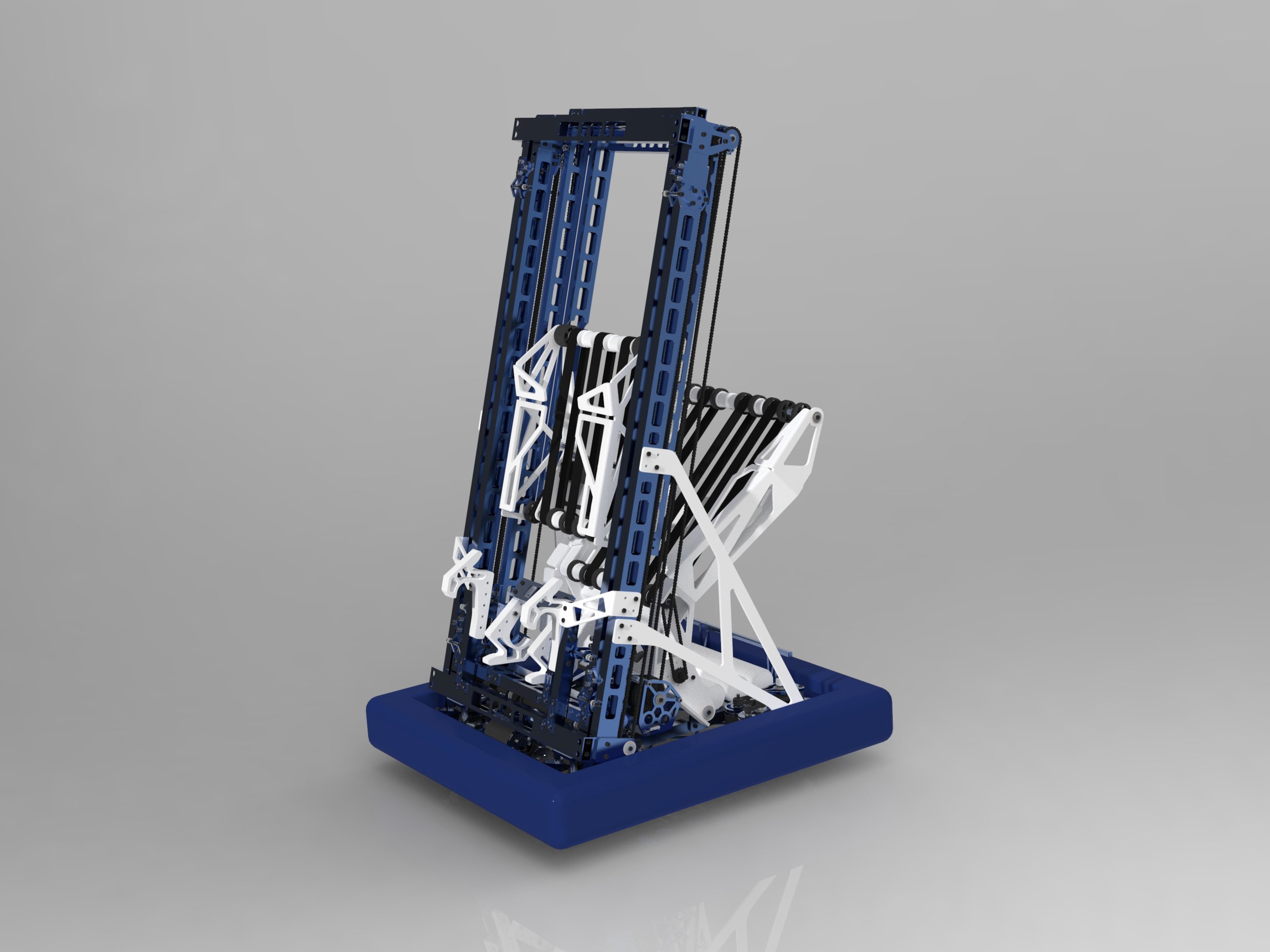
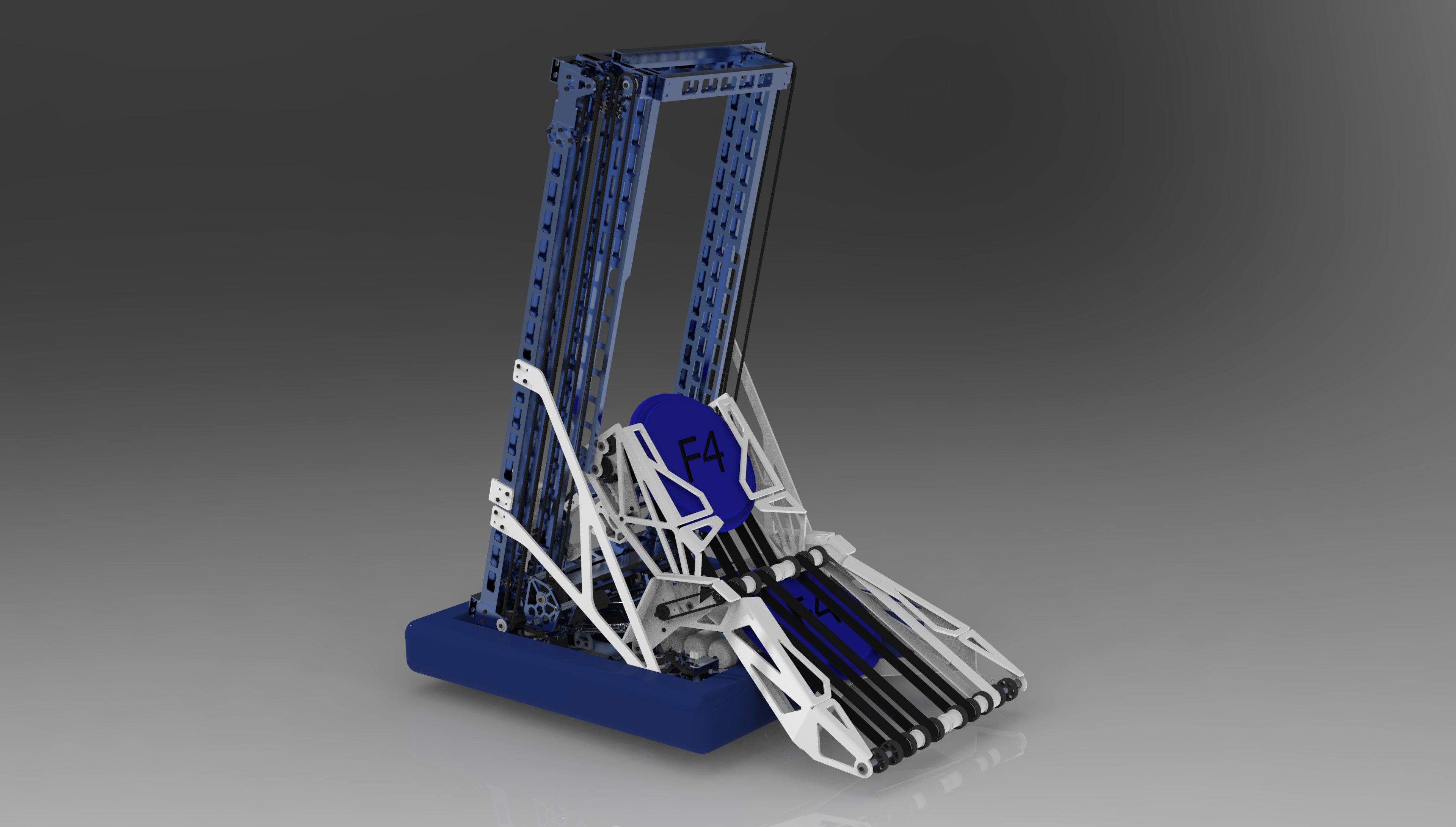
My robot’s design can be split up into three main subassemblies: the drivetrain, the elevator lift, and the disc manipulator. The drivetrain is a compact variation of a swerve drive design. The swerve drive consists of four independently controlled pods. Each pod consists of a driven wheel on a powered turntable. In other words each wheel can be independently steered to point in any direction to drive the robot. While swerve drive is one of the most mechanically complex drivetrain systems and requires 8 entire motors to work, it was the most maneuverable option. Swerve drive is also one of the only multidirectional drives that can resist defensive play from other robots reasonably well.
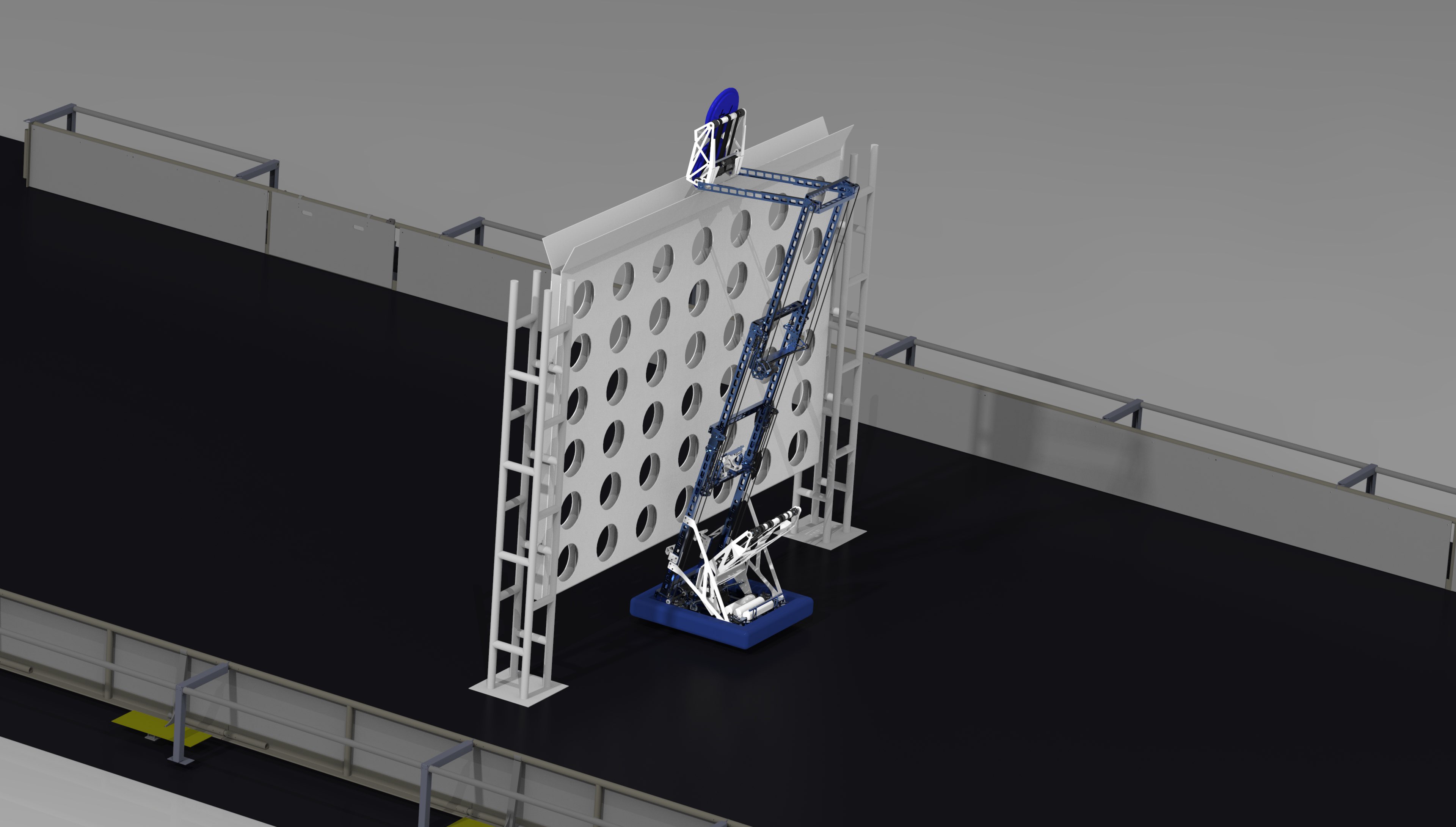
The elevator lift subassembly consists of rectangular tubes on bearing rollers powered by a cascading chain drive. Three CIM motors extend the two-stage elevator lift to maximum height in a theoretical 1.5 seconds. Each of the rectangular tubes are cnc-lightened to reduce weight and keep the center of gravity low. On the last stage of the elevator lift there is a swing arm powered by two more 775 class motors. The swing arm adds an extra degree of control when depositing. The elevator is angled slightly so that the robot can zero with the bottom of the scoring board while depositing for quick alignment.
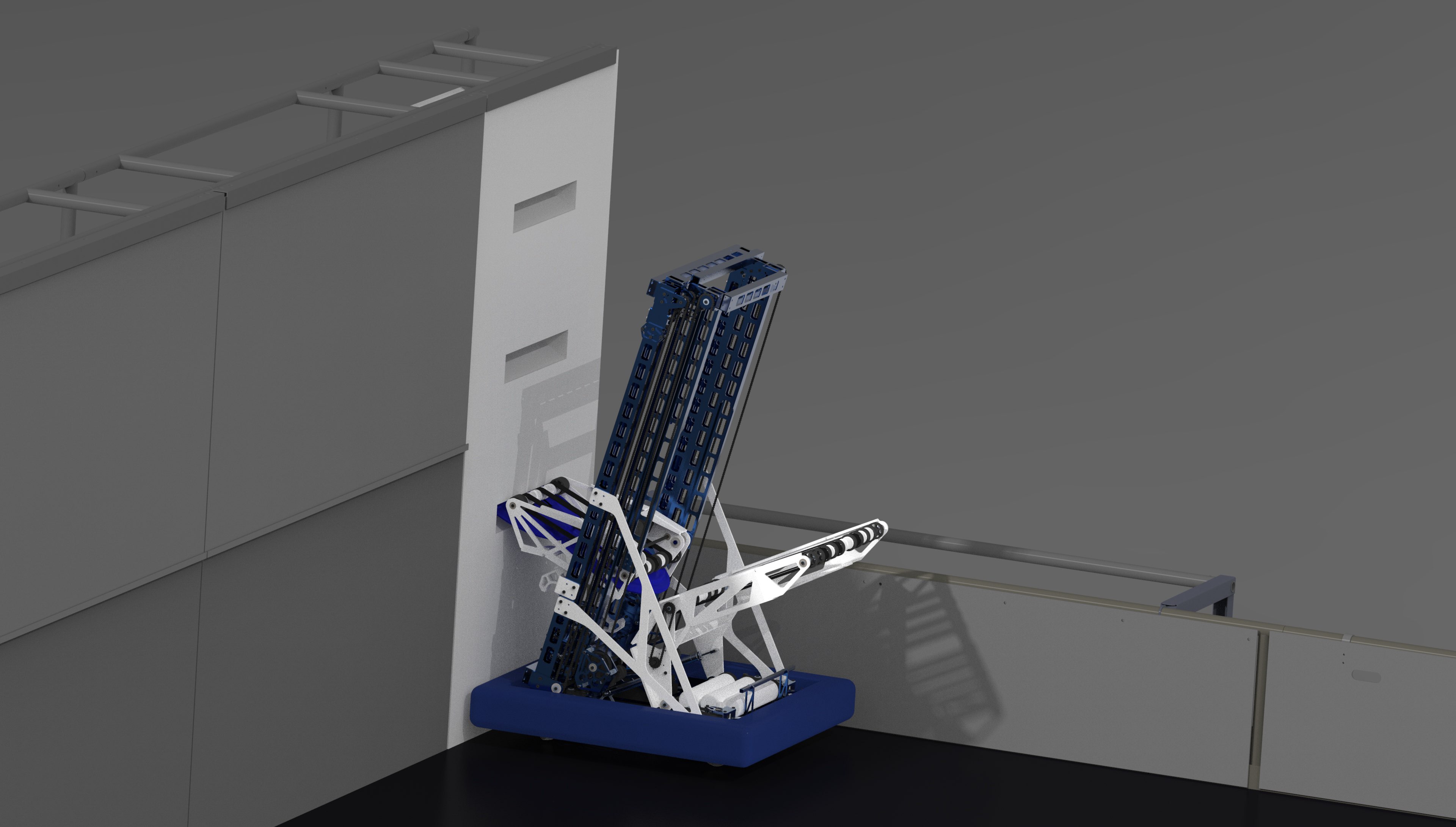
The disc manipulator consists of two parts: the lower section directly attached to the drivetrain frame and the upper section attached to the end of the swing arm. The lower section of the disc manipulator is responsible for collecting discs from the ground. The end of the lower section intake takes up the entire width of the robot to make it as easy as possible to pick up discs. The upper section of the disc manipulator can either take discs from the lower section when picking up discs from the floor or take discs directly from the wall deposit slots. Since the upper disc manipulator is attached to the end of the swing arm attached to the last stage of the elevator lift, it can rise up to above the scoring board to deposit the discs.
After 72 hours of hard work with very little sleep, I placed third place overall. I’m not sure how many teams actually submitted a robot design, but I do know that at least 200 people registered for the competition. While this challenge was some of the most intense designing I’ve ever done in such a short period of time, I learned a lot about my own capabilities.
Skills Enhanced
- CAD (PTC Creo Paramtric)
- Rendering (Keyshot)