2019 Valor Cad Competition
This is my submission to the first Valor Cad Competition (VCC). This robot was designed to FIRST Tech Challenge (FTC) rules and specifications to play in a virtual game challenge. The layout of the challenge was very similar to the previous robotics CADathons, but this robot design requirements are a much smaller maximum starting size. Teams of one to three students were given five days to plan, design, render and document a robotic solution to the challenge. I didn’t know anyone in FTC that primarily used the same cad program as me, so I decided to register as a solo team.
This challenge was called Supershot. The premise of the game was to pick up small discs and launch them into a goal on the other side of the field. Other robots could also play defense and block shots in certain positions, so the robots had to be maneuverable. There was also some difficult terrain near the center of the field that the robots had to drive over to score points. Normally matches are two minutes and 30 seconds long. The last 30 seconds of the game is called end game and in the end game, the robots can climb on to the goals and lift off the ground to score extra points. Since these games are virtual and no one was required to physically build their robot in such a tight time constraint, the robot designs were judged by a panel of judges.
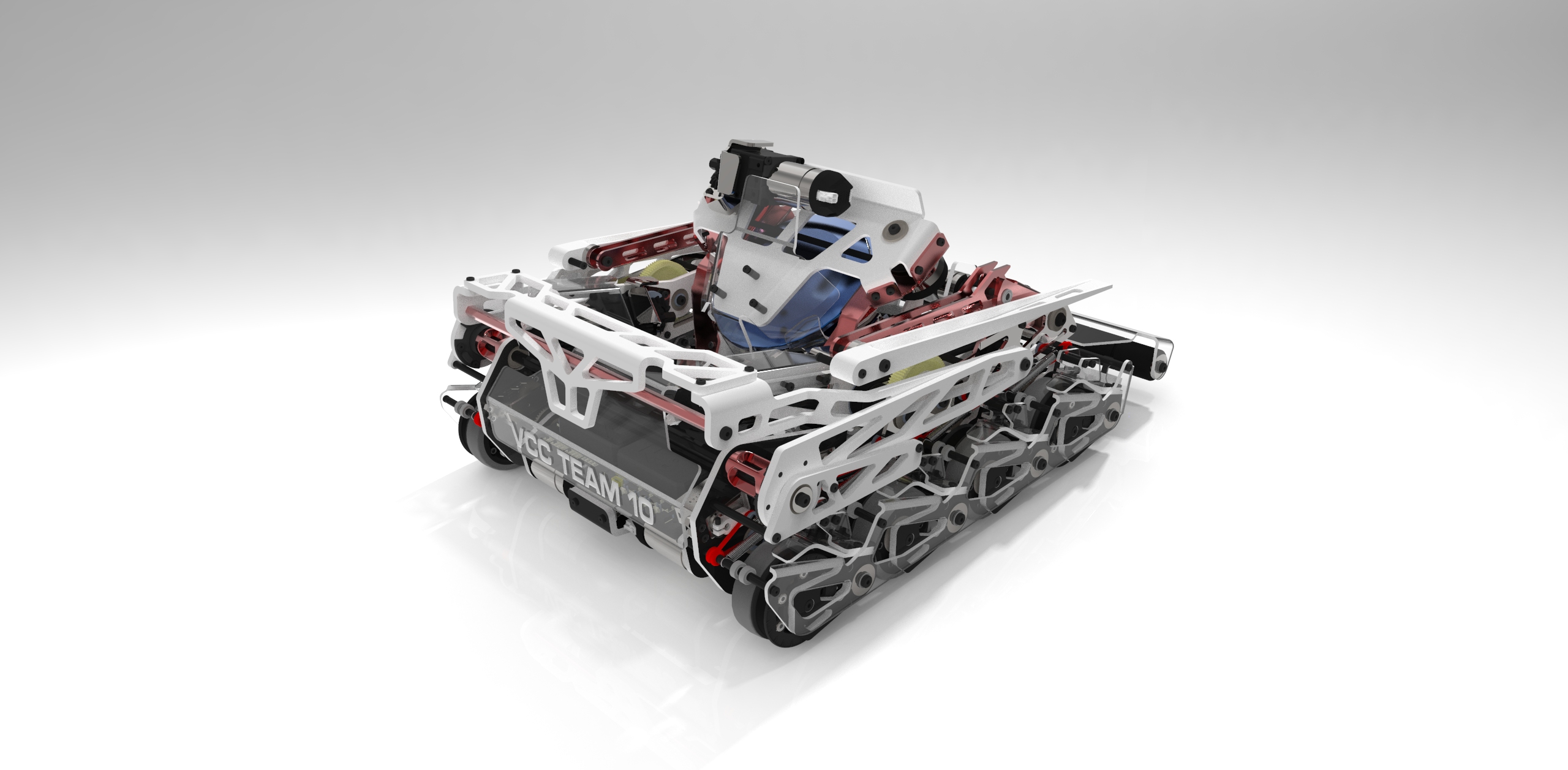
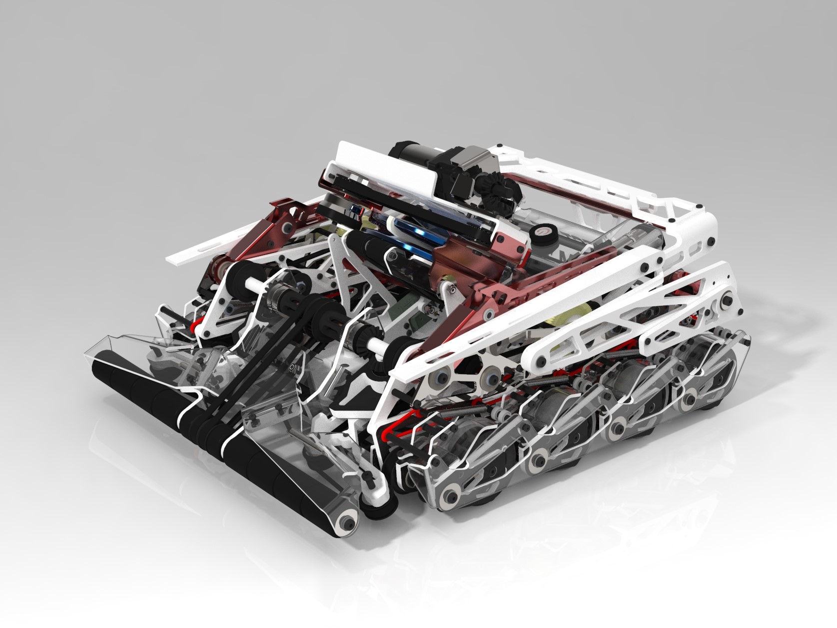
After about a day of planning, I decided to go with a really ambitious design. The drive train would have independent suspension inspired by cantilever tank suspension to go over the difficult terrain. A retractable wide intake would be in the front to grab discs into the robot. Directly behind the intake and in the center of the robot is the turret mechanism that houses the disc loading and shooting mechanism. The rear and sides of the robot above the drivetrain would be for the end game mechanism for climbing the goal and lifting up a partner robot. Since I could’ve assumed a virtually infinite budget for the bill of materials and assumed that I could’ve had access to any machinery, I went all out. Most of the aluminum parts on this robot would be waterjet cut then bent on a cnc brake. Some polycarbonate pieces would also be waterjet cut then bent with a heat bender. A few parts were 3d printed or cnc milled.
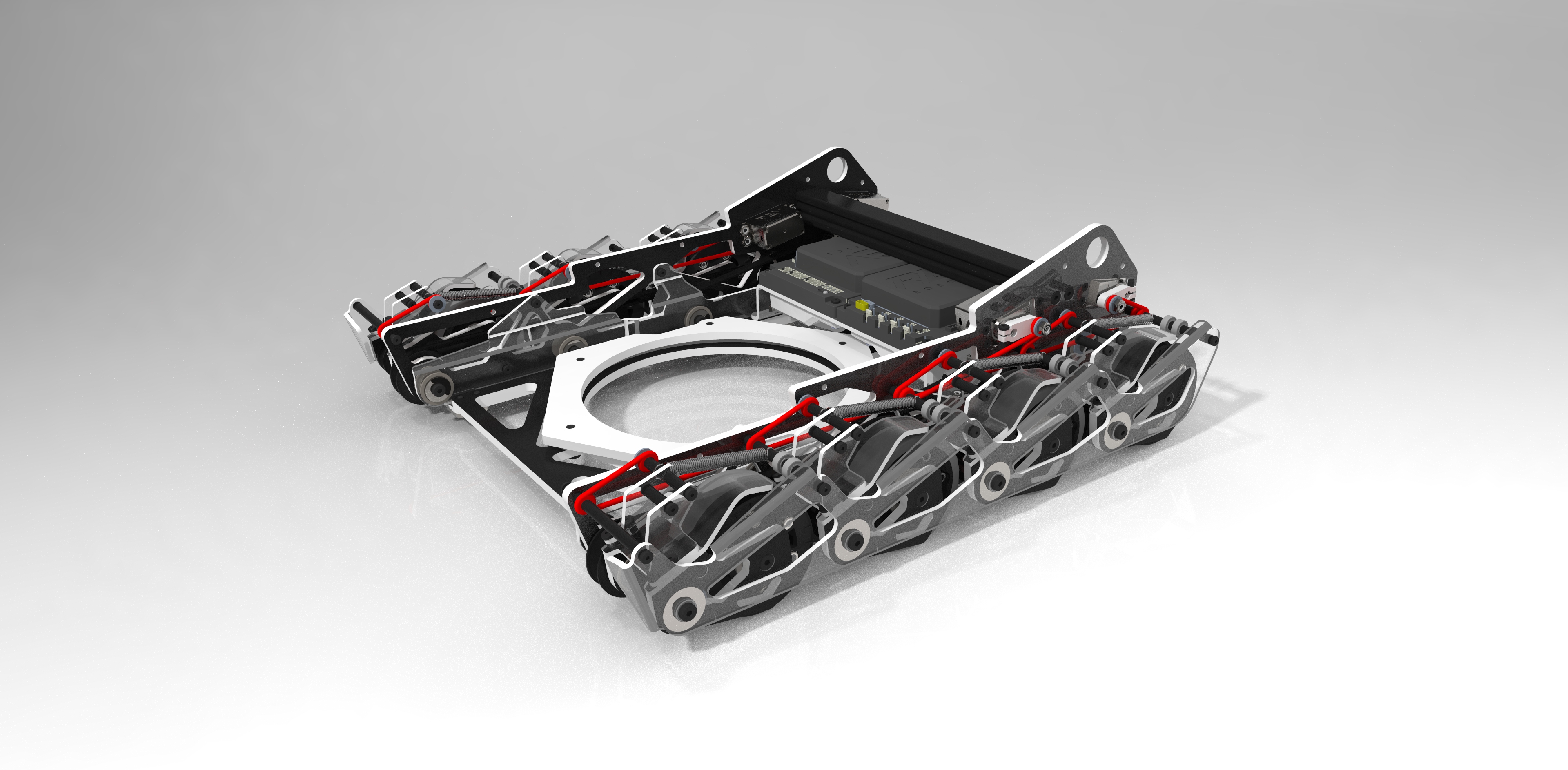
The eight wheel drivetrain is quite special. Four motors in total powered all eight wheels belted together. Each wheel is housed in its own suspension pod that each have about 1.5 inches of travel. The suspension pods float on a separate drive shaft and adjustable spring system. Four high torque servos control the ride height of two pods each through a cord tensioning system. The entire drive train would be made of waterjet aluminum and polycarbonate for rigidity and impact resistance.
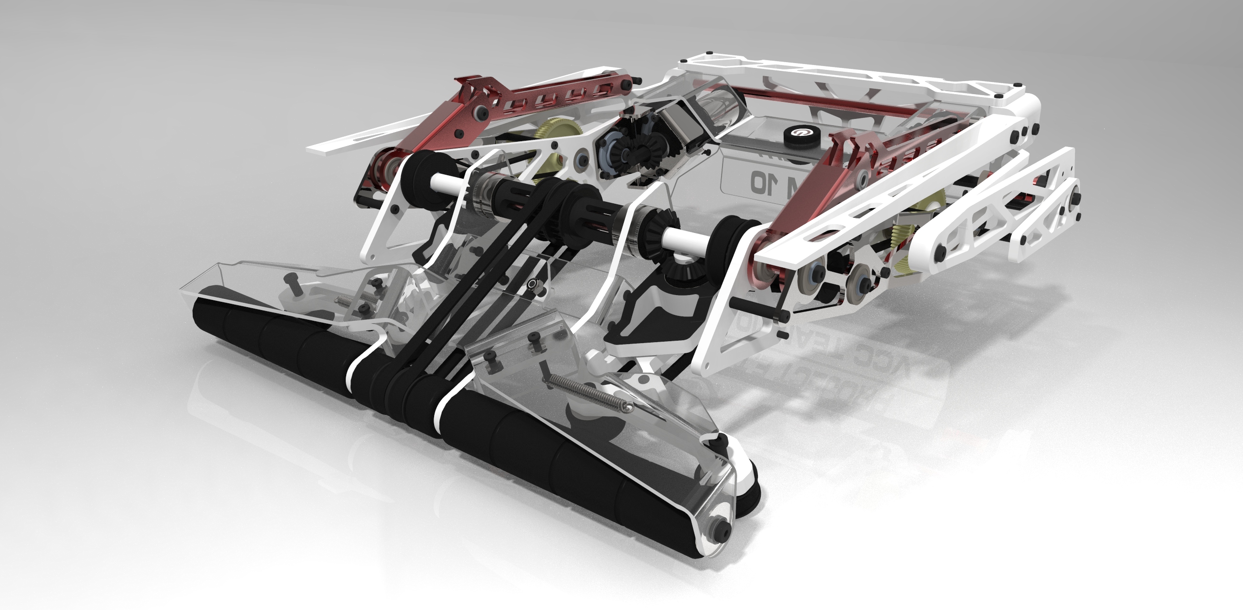
The retractable intake would feature a really wide front spanning the entire width of the robot to make it easy to pick up discs. A servo linkage retracts and extends the intake along a pivot axis. Belts on the bottom of the intake center the discs before they enter the robot. All the rollers and belts are geared to move together to be powered by the same motors. The centering belts are sprung together to create a sort of preload when the discs go through making sure there is contact with the discs throughout the whole transition into the turret. Shaped polycarbonate and 3d printed parts are used on the intake to make it lightweight and flexible to withstand impact with other robots and field components.
Directly behind the intake mechanism is the turret assembly which spans the entire height of the robot. There are two mechanisms inside of the turret, the disc loading and shooting mechanism. Since opponent robots could try to block your shots, it was advantageous to have the shooter mechanism as high as possible. The loading mechanism doubled as a lift system to raise the discs up to the shooter mechanism from the low intake height. Discs are loaded only when the turret is facing forward. Robots were only allowed to control two discs at a time, so the loading mechanism only has enough room for two discs. A compact flywheel shooter design was chosen due to turret space restrictions. The entire turret mechanism has a total travel of slightly under one full rotation.
The end game mechanism shares two motors with the intake mechanism through a one-way-bearing power share gearbox. Both the climbing mechanism and partner “forklift” are sprung outwards and released by a servo. When the power share motors rotate in one direction, the intake is run and when the power share motors rotate in the opposite direction, the climbing mechanism is winched down to raise the robot.
Since I had a longer time limit to spend on this robot design with five days instead of three days to do everything, I took my time and made sure each part was refined. I scored second place overall out of about 60 submissions. I had a lot of fun designing this robot and thought it was a couple days well spent.
Skills Enhanced
- CAD (PTC Creo Paramtric)
- Rendering (Keyshot)