2019 Winter F4 CADathon
This is my submission to the 8th bi-annual CADathon hosted by F4. Like the past F4 CADathons, my robot was designed to FIRST Robotics Competition (FRC) rules and specifications to play in a virtual competition. Teams made of one to three designers from around the world were given 72 hours to plan, design, render and document a full FRC class robot. Since I had entered as a solo team in the previous two CADathons, I decided to keep the trend and enter solo again.
This challenge was called Power Play. The game challenge was based loosely around the game of ice hockey where robots had to pass a puck across the field to team robots and score into the goal while avoiding opponent robots. The pucks were fairly large and heavy at 8 inches in diameter, 2.75 inches in thickness and 3 lb in weight. The robots are required to pass to each other to advance down the field. There is also a zone near the goals called the goalie zone where robots can extend up to 4 feet tall. Otherwise, robot size is restricted to a 36 in by 40 inch by 24 inch tall box. A lot of complex mechanisms have to fit in that size constraint.
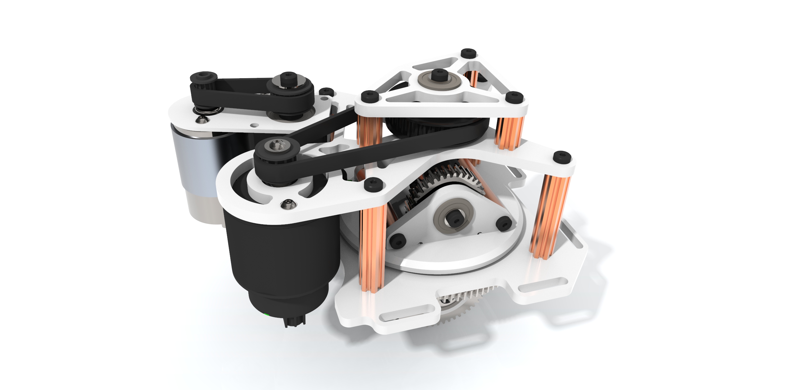
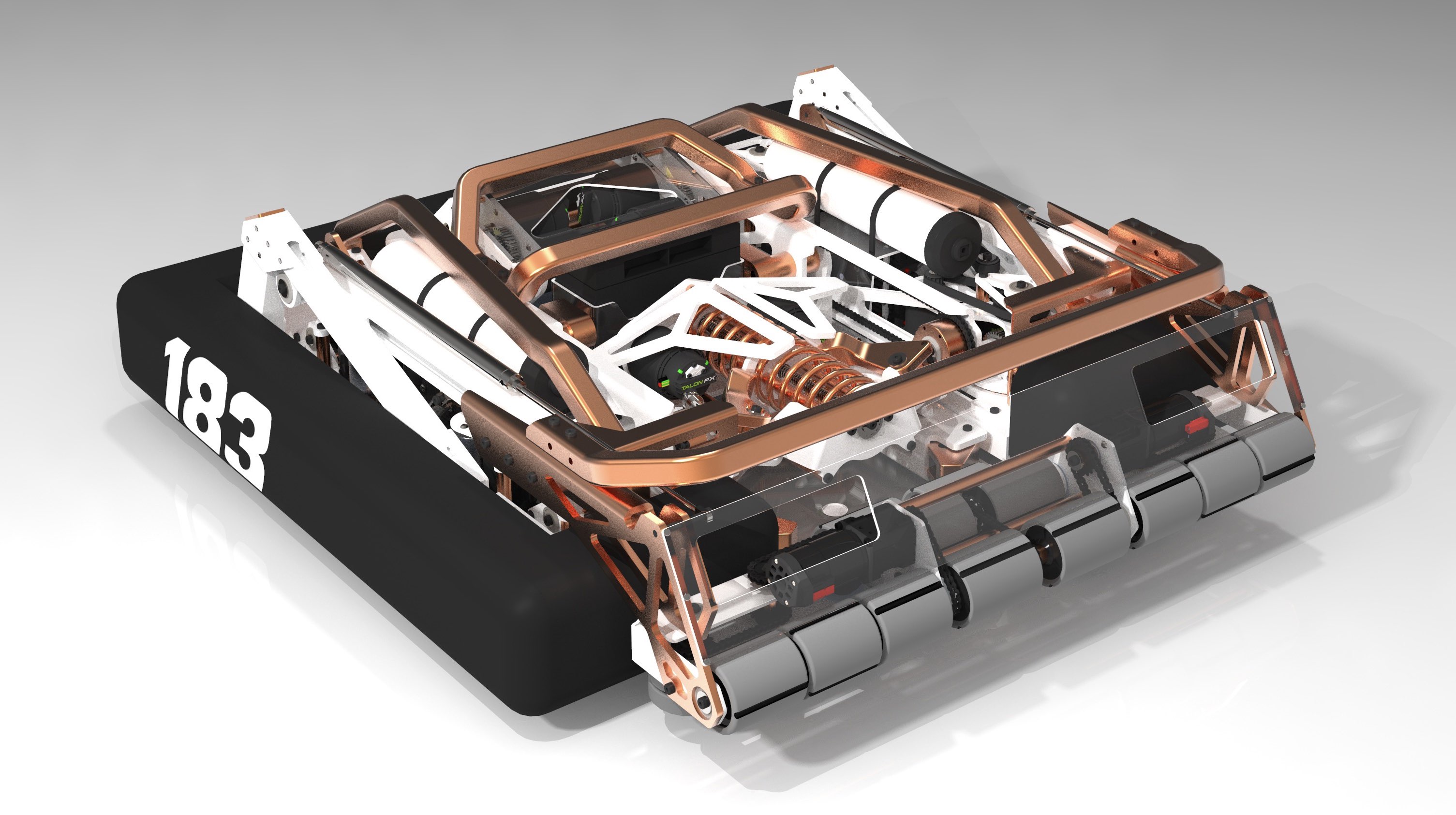
My robot design can be split up into four main subassemblies: the drive train, the intake, the puck launcher and the aiming system. The drive train is very similar to the swerve drive train I used in my first CADathon, but with a couple changes. Swerve drive trains usually have 4 independently driven and controlled wheels. Each wheel has the ability to rotate in place to change direction. The first change I made was to switch out the brushed CIM motors with brushless Falcon 500 motors. Swapping out the CIM motors lightened the weight of each module and let me lower the height of the entire module. The Falcon 500 motors also have over double the power output of CIM motors, so I redid the gearing to improve both top speed and acceleration. Along with lowering the total height of the assembly, I redid all of the pocketing to reduce weight and make all the plates easier to machine. Decreasing weight, lowering the center of gravity and increasing the power of this assembly will only make the robot more efficient.
The next assembly is the intake, which takes up the entire width of the robot. The image above shows the robot in orientation to intake a puck. Along with making it easier to intake pucks, the width of the intake can be used to block opponent passes and shots. Since the entire intake is actuated along two degrees of freedom, it can rise up to 4 feet in the goalie zone and block shots. The swerve drive train lets the robot move side to side to block shots with the whole width of the intake. When the intake is in the lowest position, it can pick up pucks with multiple rollers all powered together. The dual purpose of the intake for both blocking and picking up pucks makes it a good use of the limited number of actuators and space on the robot.
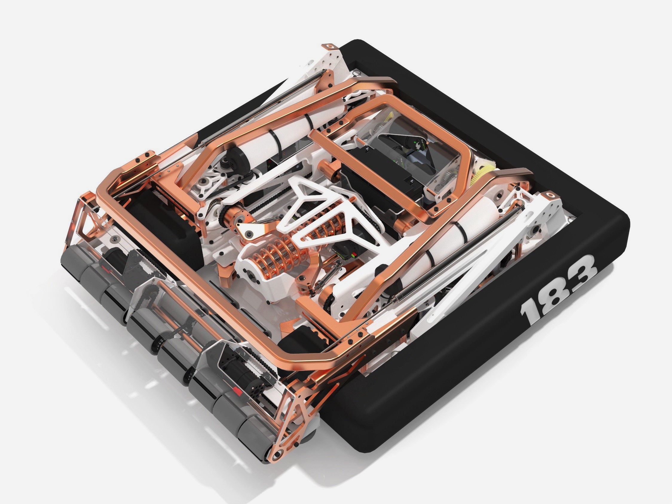
Right behind the intake is the puck launcher mounted to the aiming mechanism. The puck launcher, like the name suggests, launches pucks. Before the puck enters the robot, two Falcon 500 motors compress the large launch spring by spinning a lead screw with a plunger. The end of the spring is attached to the launch carriage that will propel the puck out of the launcher. When the carriage moves into the charged position, pneumatic actuated fingers lock it in place. After the puck is passed off from the intake into the puck launcher, two more little fingers move in front of the puck to keep it in place until right before launch time. Right before launch, the plunger on the lead screw moves to a certain position to control launch power. Moving the plunger changes the spring’s maximum travel distance which changes the distance available to accelerate the puck.
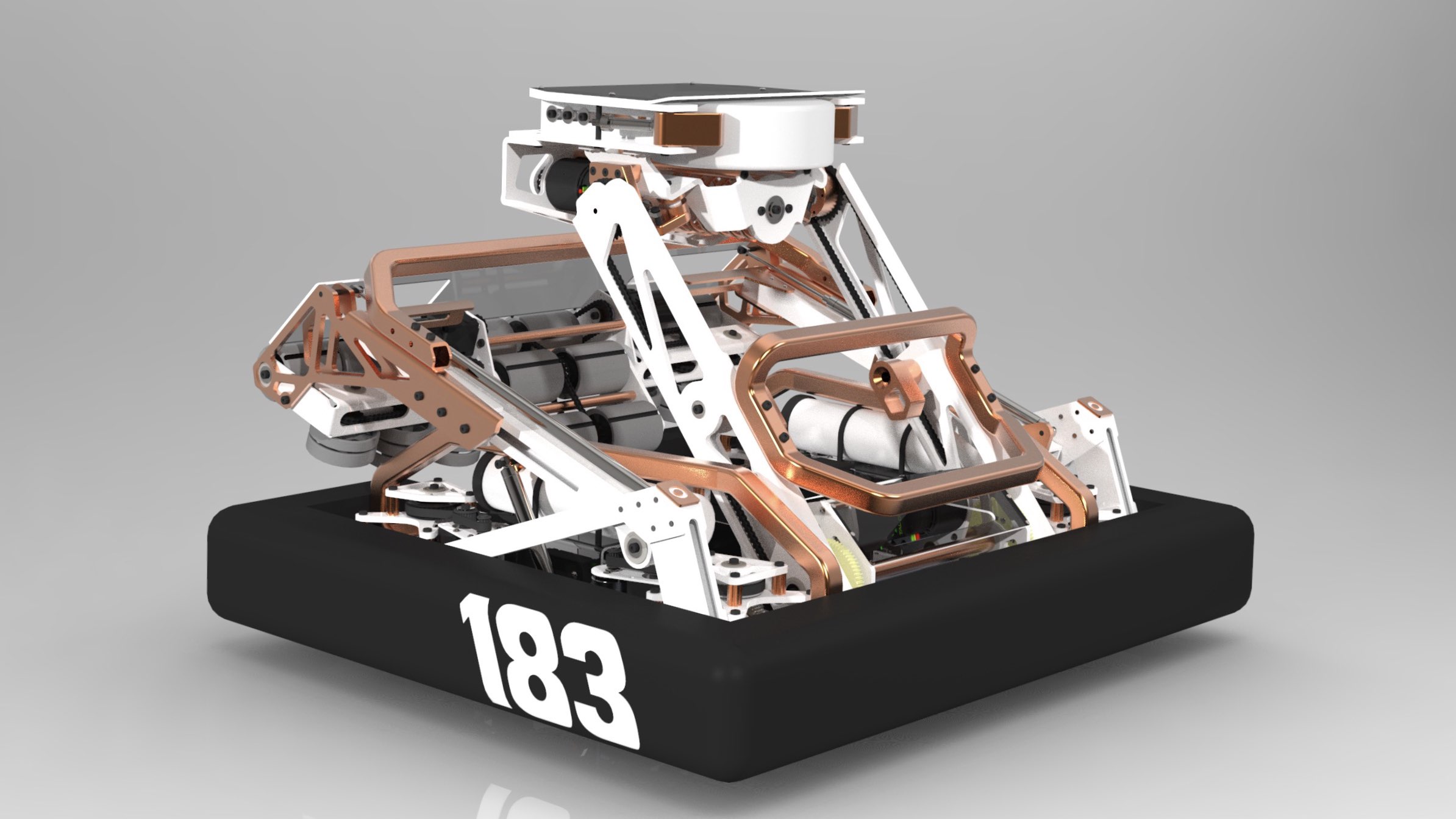
Crucial to controlling the puck launcher is the aiming mechanism. While the drive train is responsible for turning the robot to the direction, the aiming mechanism is responsible for launching angle and height. The aiming mechanism consists of an arm actuated by four entire brushless motors. The reason for dedicating four entire motors is so that the arm can move to any position in less than a theoretical calculated 1.25 seconds. This means that the robot should be able to intake and launch the puck in less than two seconds, which is very quick. When the robot is loading, the aiming mechanism positions the puck launcher facing forwards right behind the intake mechanism. Right after the fingers lock the puck in position, the aiming mechanism is free to move around. Most often the aiming mechanism will flip the puck launcher 180 degrees and lift the height up 12 inches to launch the puck backwards and clear the rest of the robot. Turning just the launcher 180 degrees to launch backwards is much faster than turning the entire robot 180 degrees using the drive train. The aiming mechanism can also raise the launcher all the way up to the maximum two feet to launch over any opponent robots. The Image above shows all of the mechanisms oriented to launch backwards at max height.
Overall I was extremely satisfied with this robot design. I think this is the best looking robot I have ever designed and it is going to be difficult to design something more aesthetic. Comically, I placed third place again, for the third time in a row. I guess you could say that my design performance was consistent, but the competition gets harder each time with more participants submitting at each CADathon. This was my last F4 CADathon submission and I couldn’t have been happier with what I came up with in four days.
Skills Enhanced
- CAD (PTC Creo Paramtric)
- Rendering (Keyshot)