Electric Longboard V2
I’ve gotten hooked on electric skateboarding. To go to class, to get food, to get groceries, to meet up with friends, I find myself grabbing my electric skateboard almost every single time. After a couple months using my first e-board, it’s time for a total upgrade. There is this immense hill in the middle of campus that my first e-board struggles to get up. I also wouldn’t trust the single motor setup on my first board to brake the entire way down without failing. With no redundancy in the system, if the belt loses tension, motor controller overheats, or battery regen overloads, the brakes will fail and I will most likely fall. My first eboard was focused on budget and portability, but my second eboard will focus on performance, comfort and reliability.
I had a few things in mind that I knew that I wanted on the new eboard at the start of designing. In terms of performance I wanted to have a dual belt motor set up for increased acceleration, stopping power, and reliability. Since the stopping power limiting factor on the single motor setup of my first eboard is the friction between the powered wheel and the ground eventually sliding out, adding another powered wheel practically halves the stopping distance. I also wanted a higher voltage and capacity battery for more power and range. As for comfort, I decided to go with a flexible fiberglass reinforced bamboo longboard deck and double kingpin trucks. The flexible bamboo longboard deck will absorb some of the road vibration and give the board a nice and fluid turning motion. Despite the very long wheelbase on the 40” longboard deck, the double kingpin trucks will give the board an agile and tight turning radius at the sacrifice of some high speed stability.
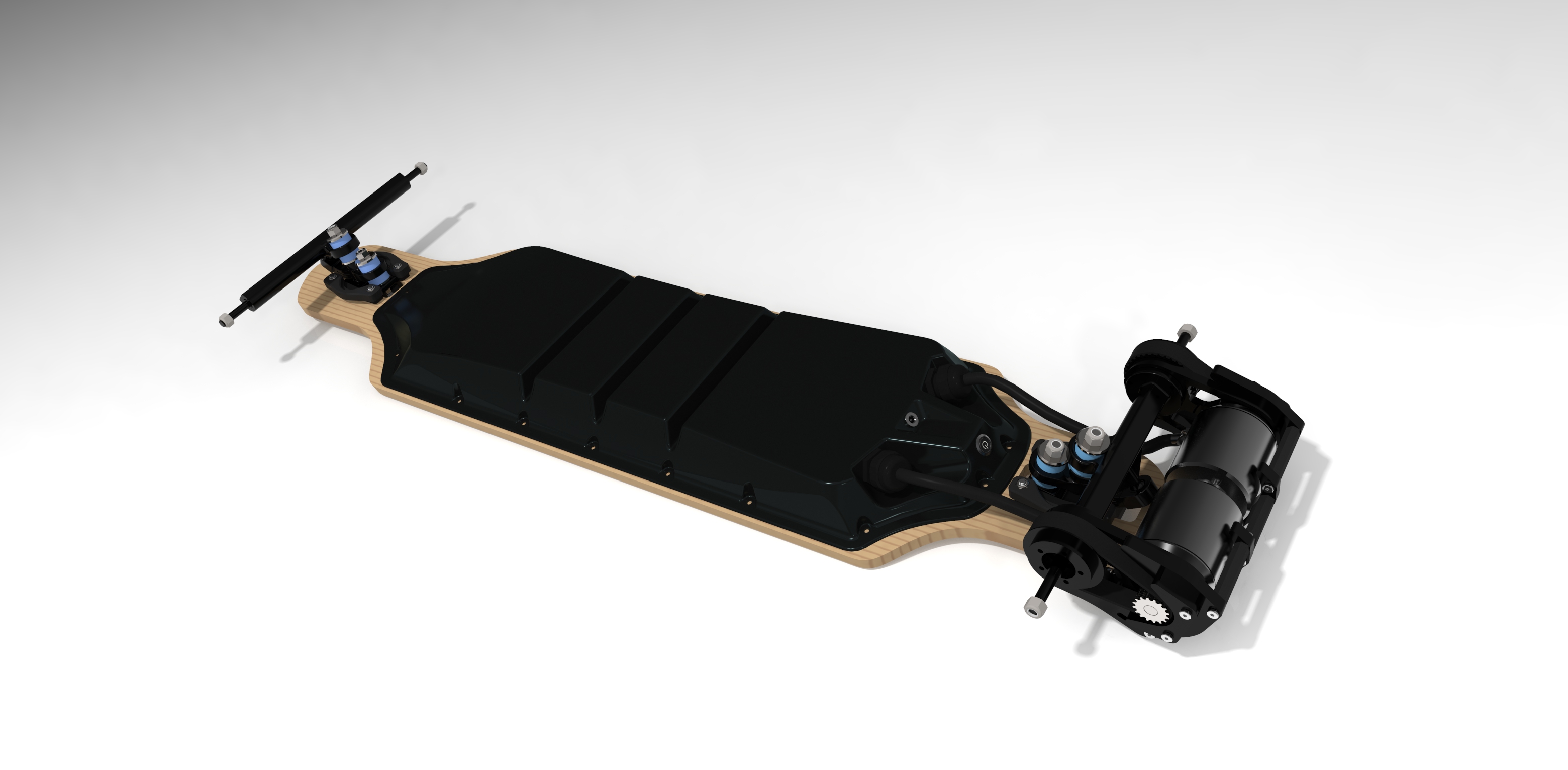
As with most of my projects, I like to lay everything out in CAD to get a good idea of what I’m getting myself into. I couldn’t find any CAD models of the deck, trucks, or motors that I was planning on using anywhere online, so I quickly modeled estimates from photos. The only thing I had on hand at the time of modeling the parts was the deck. I was able to model the subtle transverse curves to the deck to make the enclosure a near water tight fit. Everything else, including the motors, trucks, motor mounts, motors and VESC were being shipped from China by sea, which arrived nearly almost two months after I finished designing everything. The one model I needed accurately were the trucks, since they contain the main geometry controlling ride height and motor mounting angle. I sent an email to customer service early on and they graciously confirmed my photo interpolated dimensions which were close to the real dimensions. Despite only designing an enclosure and battery pack, I needed every single component of the board modeled in CAD for several reasons. The first reason is that I wanted to know how large I can make the battery and enclosure without compromising a safe ground clearance. The distance between the bottom of the deck and the ground would determine the enclosure thickness. The second reason is that I wanted to know where to place the cable glands so I didn’t need to modify the length of the motor power and sensor cables.
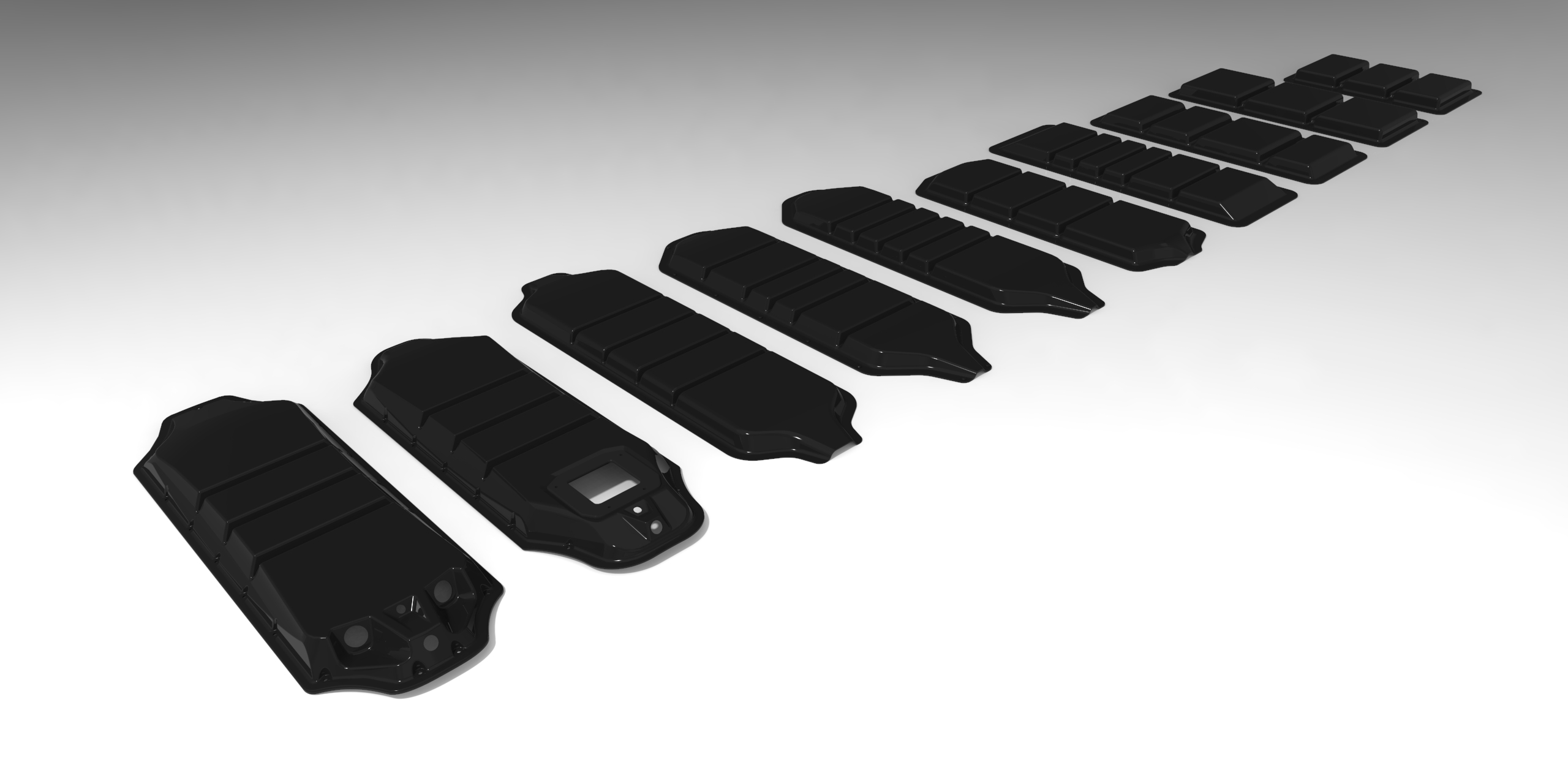
The main design challenge that I faced in this project is creating an enclosure and battery pack that won’t break when mounted to a flexible deck. Most diy eboards with flexible decks use a smaller solid enclosure and battery that only mounts to the front or rear of the deck. Their enclosures are short enough that the deck flexing won’t bend the enclosure or battery. I want a larger full length battery which means I need a full length enclosure. Many full length eboard enclosures and battery packs are available online for purchase, but they all have one thing in common. None of them are designed to be mounted to a flexible deck. All available battery packs are solid rectangular prisms that will be damaged by continuous stress caused by deck flex and most enclosures would crack. I had only one option at this point, to design and build my own enclosure and battery pack. I spent about two weeks on and off iterating battery configurations and enclosure designs until I was finally satisfied with one. My early design iterations focused on functionality and would’ve gotten the job done, but I experimented with some 3d surfacing techniques and ended up with something significantly better looking than I had anticipated.
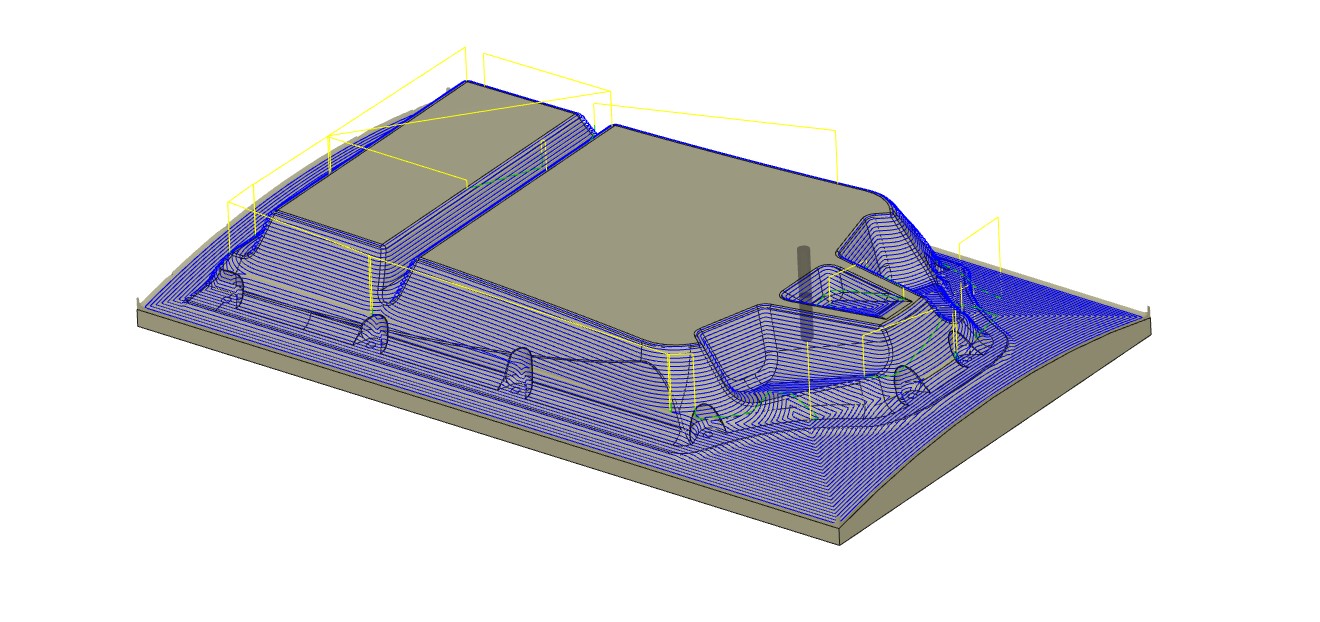
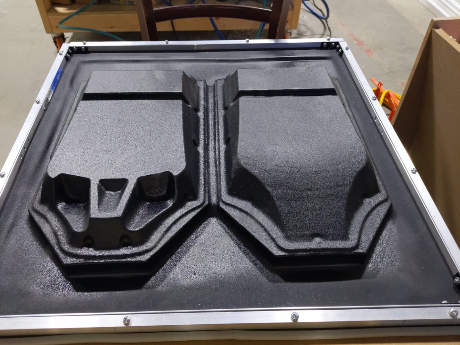
While designing the enclosure, I had to keep several design requirements in mind. I read several articles and technical documents on vacuum thermoforming to make sure my design would form correctly the first time. What I got out of those documents are the optimal corner radii, draft angles, and max draw distances. I was also working within the limits of my home made patio heater and shop vac thermoformer, so I kept things on the conservative side. I was going to CNC route the molds for vacuum thermoforming, so I also had to work within those machine’s limits. The enclosure was just under the maximum z height that the CNC router can machine. At first I was designing an enclosure to fit inside the 2ft by 2ft max CNC router cutting area and vacuum thermoforming frame area. Even with placing the enclosure along the diagonal to reach the maximum length, I was struggling to design an enclosure to fit all of the components. It dawned on me that I can split the enclosure in half and make a two piece mold. After I finished the enclosure cad model, I used the internal surface to create two mold models to machine on the CNC router. I had to do some extra work to the cut off line to make sure they would thermoform correctly.
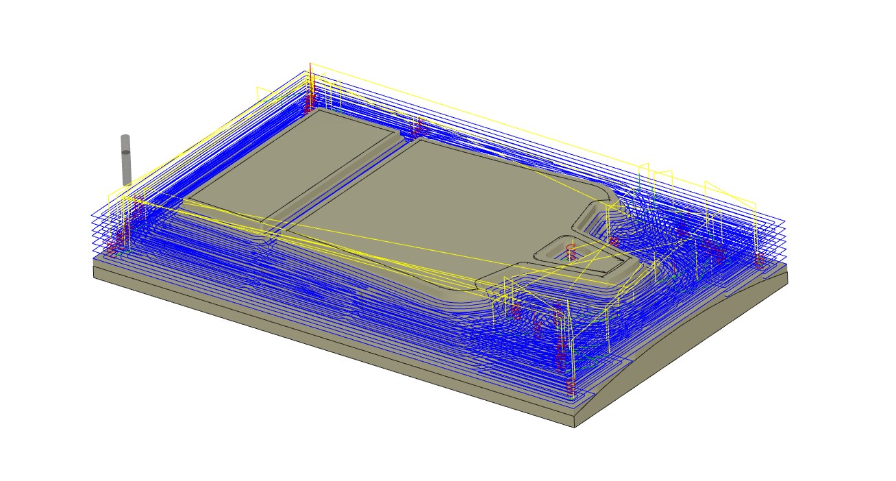
This is my second time 3D surfacing wood on a CNC router. The process was much simpler than the CNC router job for my first eboard, since I only needed to machine the top face of the mold blank. I made the mold blank stock from gluing together three layers of ¾” thick mdf overnight with a heavy weight over them. Only one tool change was needed to switch between the roughing square end mill and the finishing ball end mill. The roughing passes cut away most of the material from the mold blank.
The finishing pass was done with a ball end mill to reach into all of the complex 3d surfaces. I debated using a scallop or parallel finishing toolpath and decided to go with the scallop tool path to increase the stepover consistency since there is a wide variation of draft angle transitions. Looking back, I could have used a smaller stepover to create a smoother finish and saved time on sanding.
The finishing pass was done with a ball end mill to reach into all of the complex 3d surfaces. I debated using a scallop or parallel finishing toolpath and decided to go with the scallop tool path to increase the stepover consistency since there is a wide variation of draft angle transitions. Looking back, I could have used a smaller stepover to create a smoother finish and saved time on sanding.
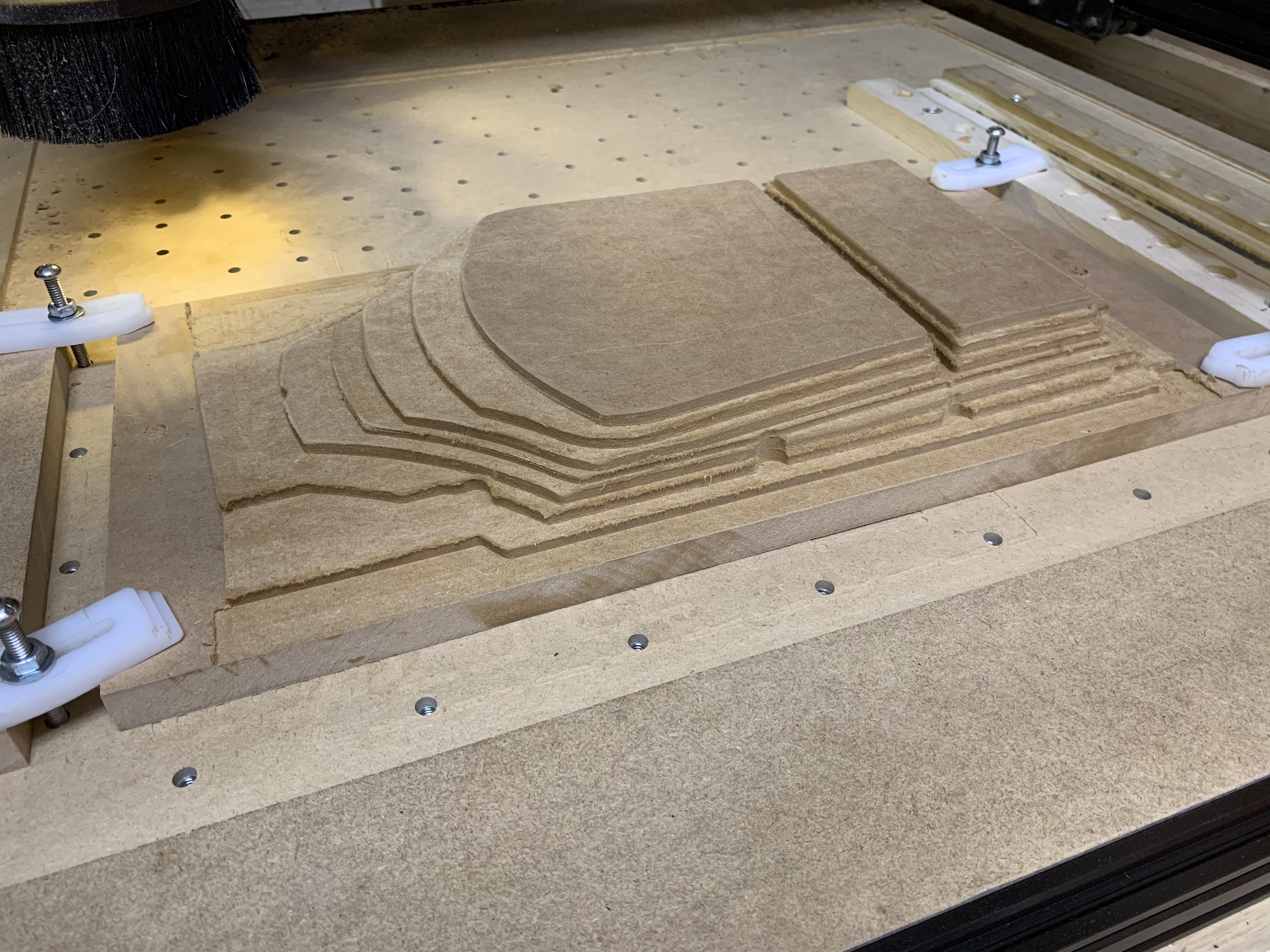
Above is an image of the mold blank after the roughing pass. You can see the square stepdowns made by the square end mill. It reminds me of how rice terraces look.
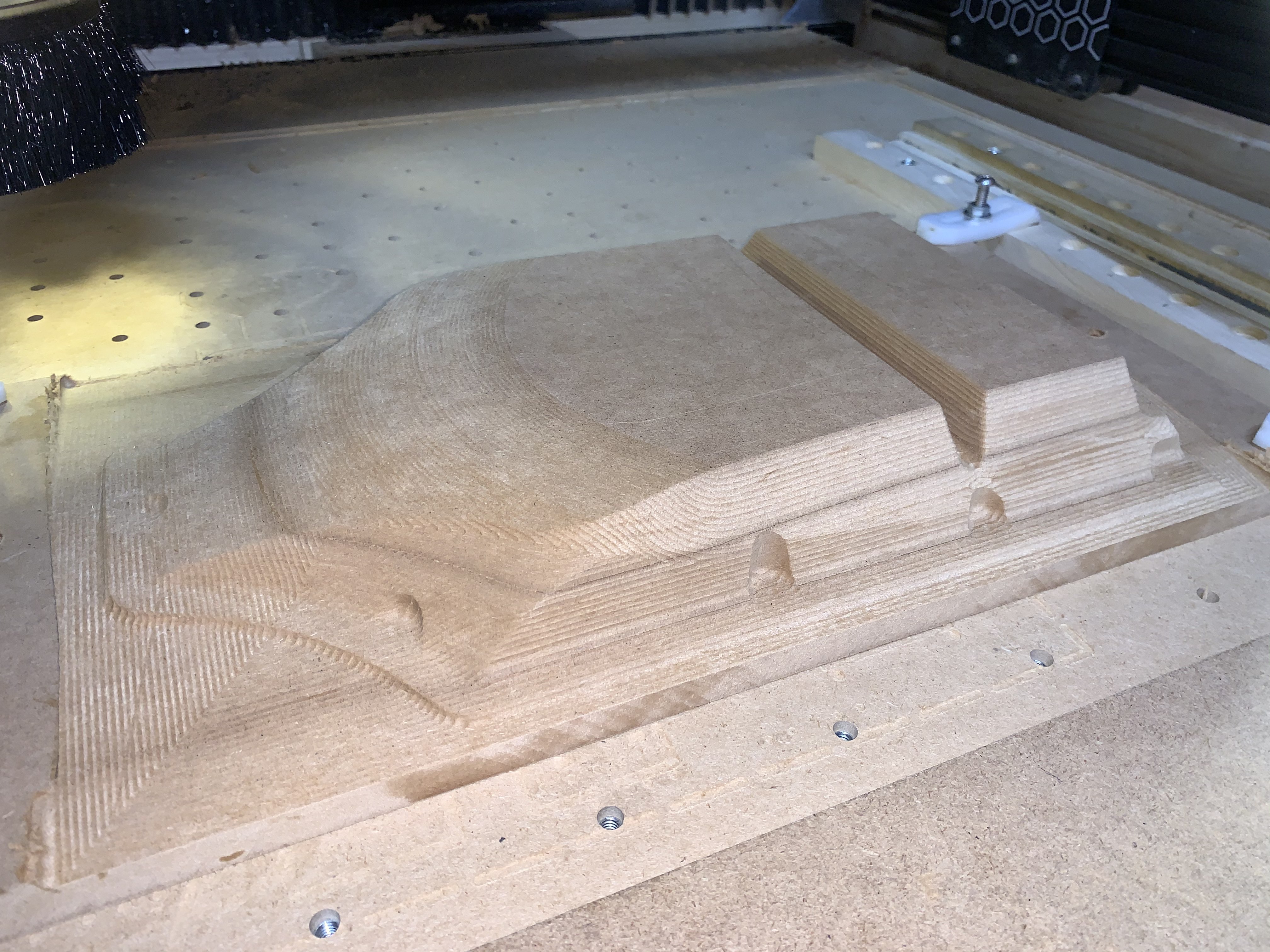
The finishing pass was very satisfying to watch as the end mill carved out the precise 3D surfaces.
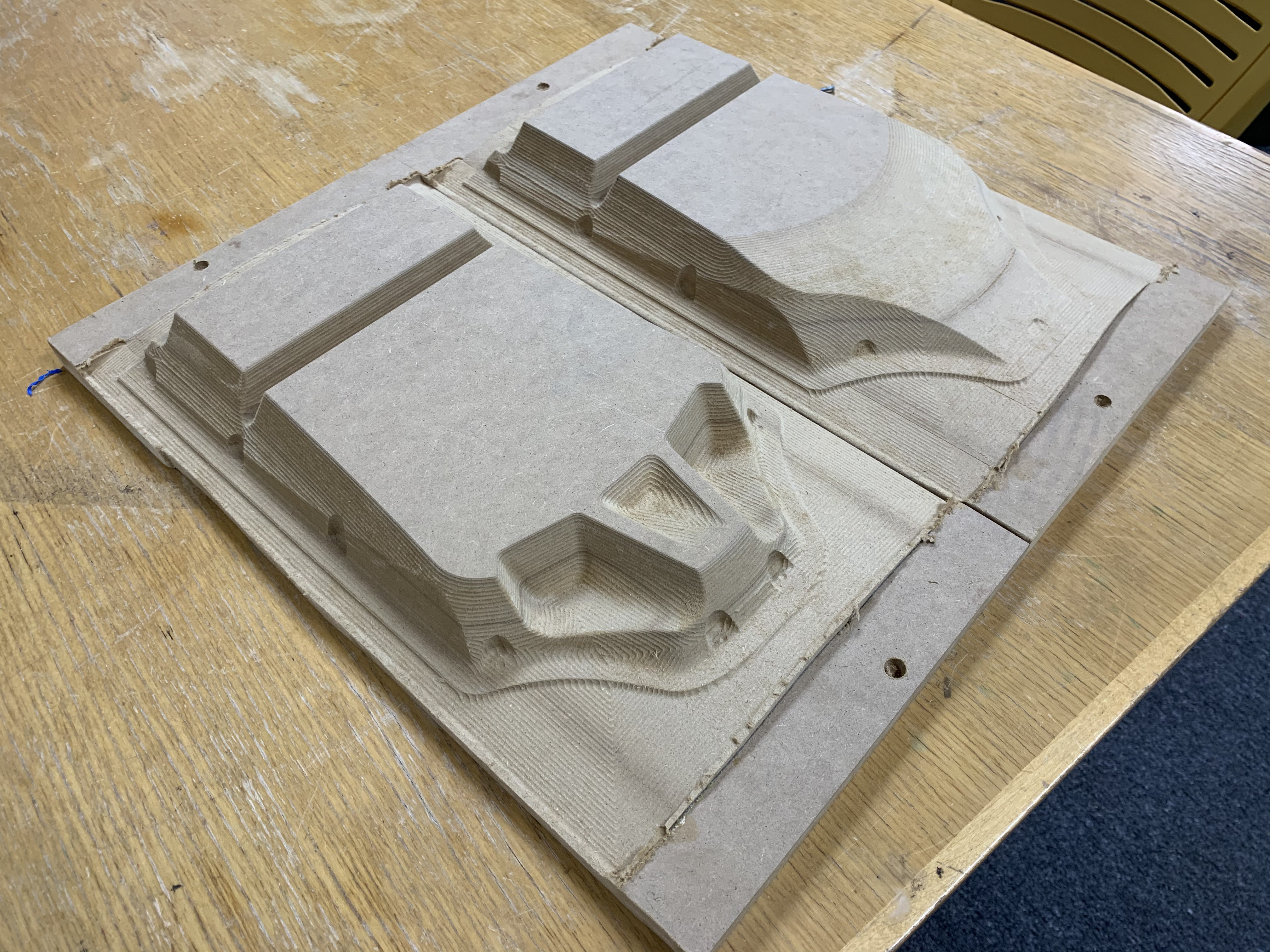
The front half and rear half molds side by side to be sanded.
The diy vacuum thermoformer consists of three parts, the plastic sheet heater, the vacuum table and the plastic sheet clamping frame. I used a patio heater at the bottom of the plastic sheet heater as the heating element. An mdf sheet box lined in aluminum foil surrounds the patio heater to evenly distribute the heat across the entire plastic sheet placed on top. Flipping the sheet once or twice during the heating process ensured that both sides were being heated and reduced sag. The vacuum table is simply a piece of mdf with a lot of holes drilled into it on top of a vacuum chamber. I used a shop vac attached to the bottom of the vacuum chamber to provide suction. There were a couple leaks, but it did not significantly affect the vacuum thermoformer’s performance with the materials I was using. The plastic sheet clamping frame is responsible for handling the plastic while being heated and formed. It is made out of angle and channel aluminum. Screws tighten the frame down onto the plastic.
The vacuum thermoforming process has three main steps. The first step after securing the plastic sheet in the clamping frame is to heat the plastic up. I placed the plastic sheet on top of the heater for a couple minutes until the temperature of the plastic on both sides reached optimal forming temperature. I got a sheet of ABS and Kydex to thermoform. ABS is faster to heat up since it requires a lower temperature to form, but Kydex is a more durable material. I used a heat gun to measure temperature at multiple points on the sheet. Once the plastic sheet reaches temperature, I hold the frame and place it above the vacuum table with the molds underneath. I have to do this part quickly with some help, because the plastic cools down within a couple seconds. After vacuuming down the plastic over the mold, the molded sheet is removed from the molds and cut down to finished dimensions on a vertical band saw. I included reference lines in the mold base to guide the vertical band saw. Holes for mounting, cables and buttons were also drilled in after sawing down to size. I was extremely satisfied with how the vacuum thermoformed parts turned out and will probably use the vacuum thermoformer again for a future project.
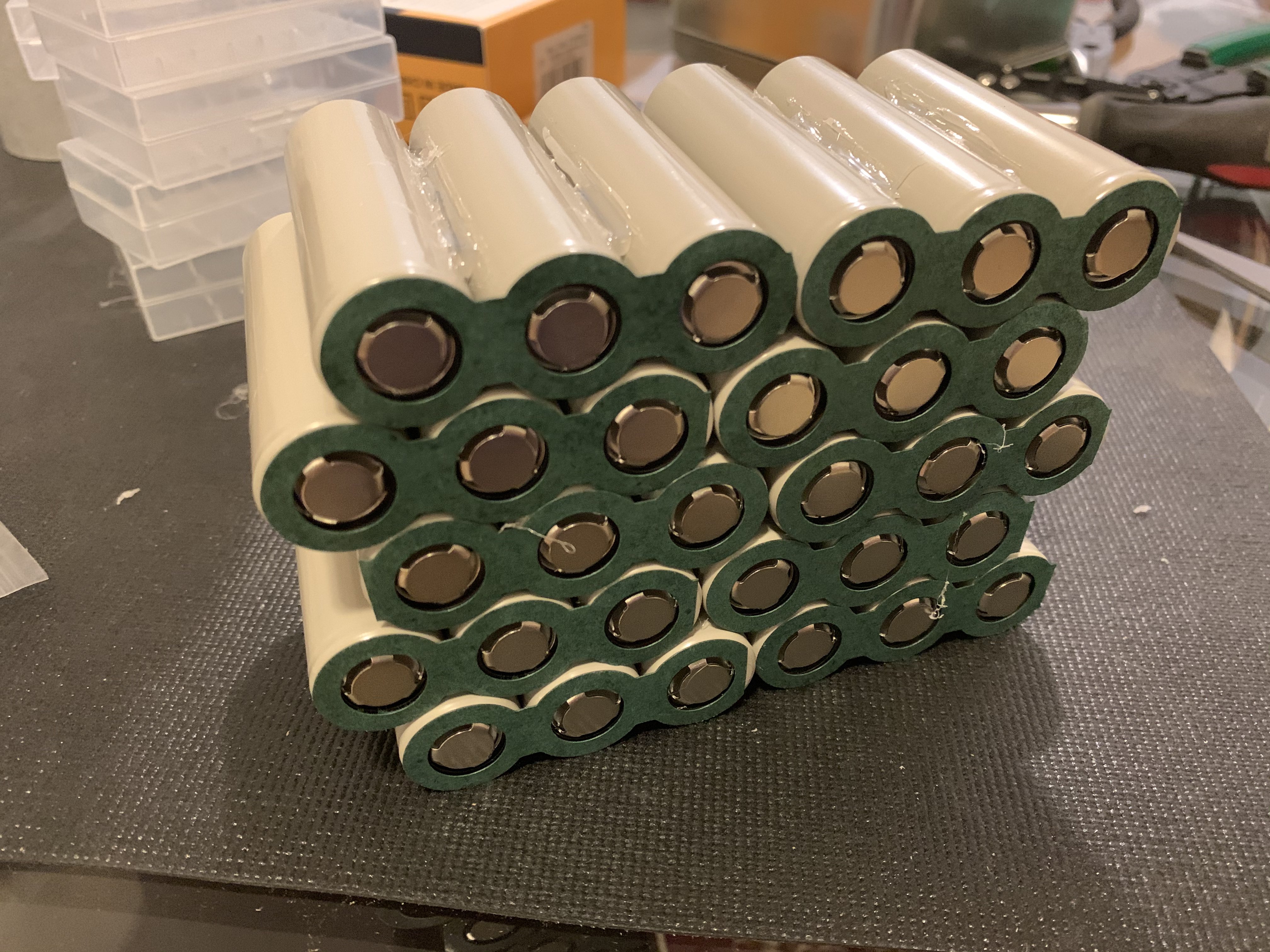
Next I made the battery pack. The battery pack consists of 30 Molicel P42a 21700 cells in a 10s3p configuration. The term 10s3p means that in the battery pack there are 10 cell groups in series and 3 cells in parallel in each group. Each cell has a nominal voltage of 3.6V, 4200mAh capacity and 45A max continuous current. To come to the decision of a 10s3p pack configuration of P42a cells, I made an entire spreadsheet comparing different battery cells and configurations for capacity, max continuous current, size, weight and cost. The 10s3p configuration I choose gives my battery pack a nominal voltage of 36V, a capacity of about 450Wh and a max output current of 135A. This is a significant upgrade from my first eboard’s 6s2p battery made out of 12 Samsung 30Q 18650 cells which has a total nominal voltage of 21.6V, a capacity of 120Wh and max output current of 30A. I had to get creative with attaching the batteries all together, since the entire battery pack has to be flexible.
The vacuum thermoformer wasn’t the only tool that I had to build for this project, I also had to make a spot welder to attach nickel strips to the battery cell terminals. I was already running close to my budget limit for this project and didn’t want to spend a couple hundred dollars on a real spot welder, so I made my own with a couple spare car parts and an arduino. There are several tutorials online for building a diy spot welder, but in summary the spot welder uses high current from a car battery through a tightly controlled timed solenoid relay to weld nickel strips to the battery cells or other nickel strip. The timing of the solenoid relay is extremely important as it controls welding power. Too much power will result in the nickel strip disintegrating and too little power results in a weak welded bond. I had to do several tests on sacrificial cells to get the timing right with the arduino. I needed to make sure that the spot welder made good welds, because I needed to make over 750 individual spot welds to make the entire battery pack. Impressively the spot welder held up through the entire process.
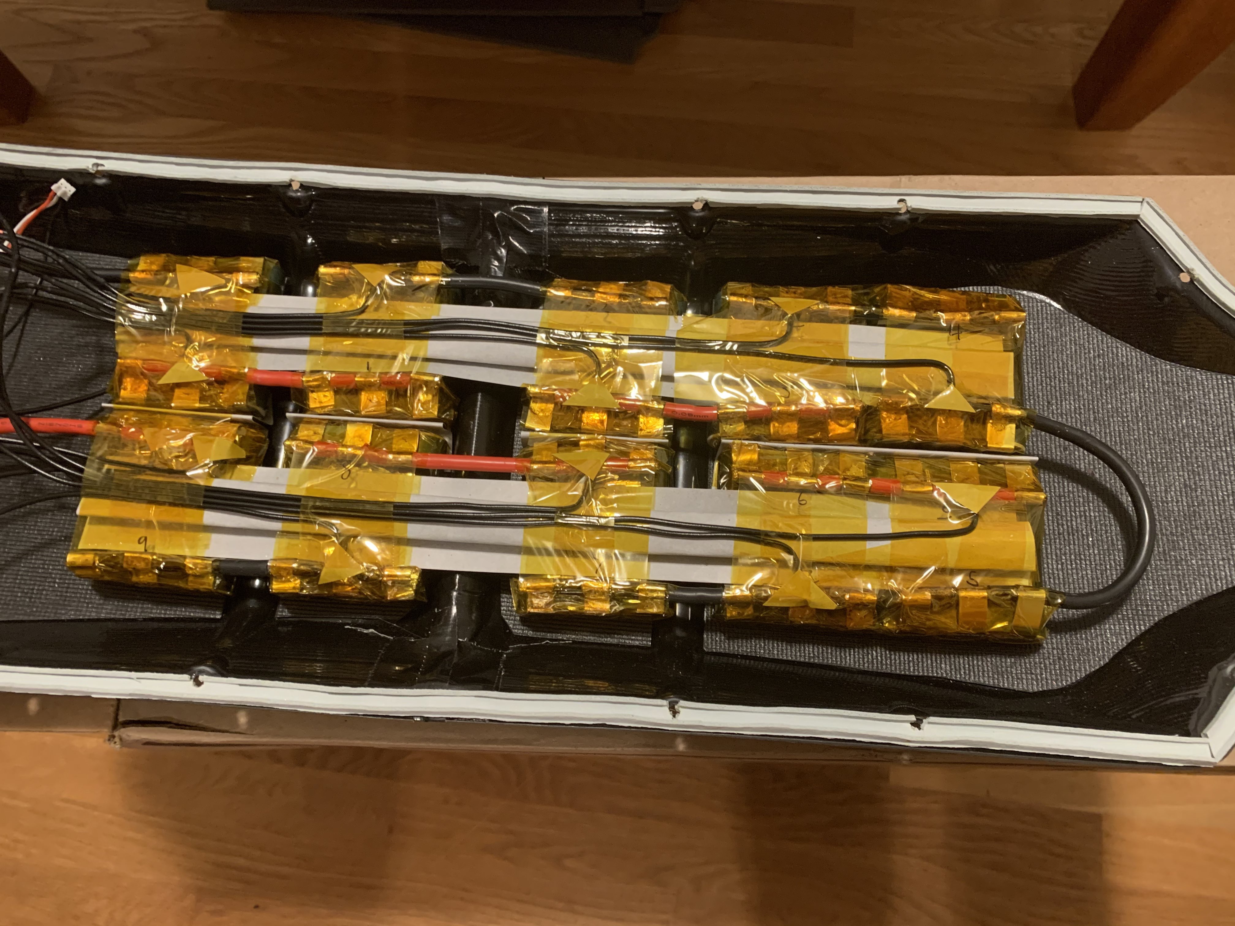
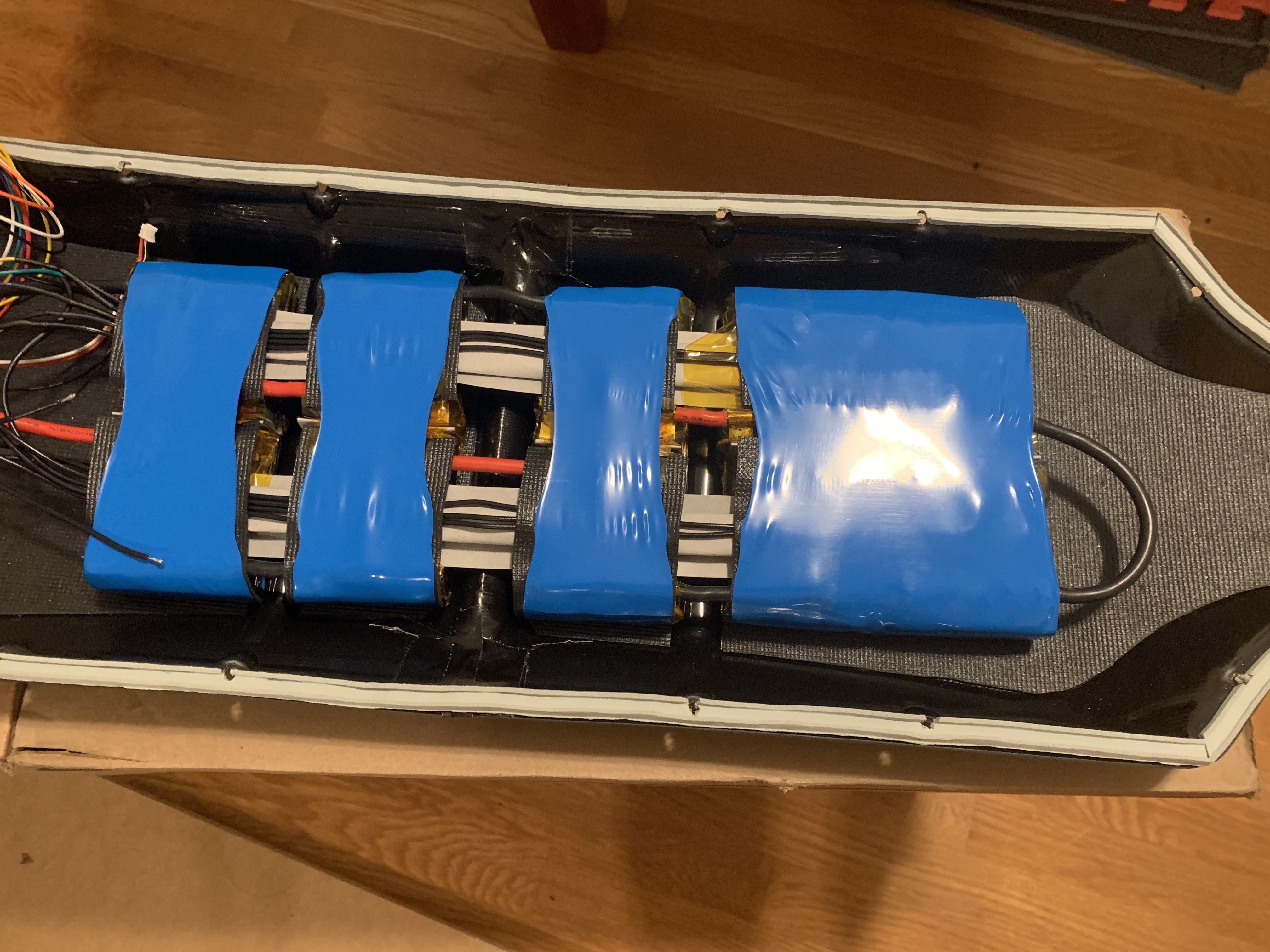
As for the battery pack design itself, I wanted something as reliable with the least possible chance of catching fire. I was really not giving myself a good time by setting tall tasks for the design requirements of my very first battery pack. The first design requirement is that I need the battery pack to flex with the enclosure and deck. Second, I need all battery connections rated to carry at least the max 135A max continuous current that the battery pack can output to reduce the chance of overheating connections. Third, I need to integrate bms wiring into a separate wiring harness to eliminate the chance of a short circuit parallel cell packs. I decided to go with a multi-layered nickel strip and copper stranded wire approach with the battery pack connections. 11 wiring harnesses were made away from the battery first. Each wiring harness is responsible for attaching parallel cell packs together and consists of one copper stranded wire with parts of its insulation stripped off and 3 or 6 sets of triple nickel strips. The main positive and negative leads only had three sets of triple nickel strips and an xt150 connector attached to the stranded copper wire. The rest of the wiring harnesses had 6 sets of triple nickel strips to attach two parallel packs together. The triple nickel strips were spot welded to each other before being partially rolled, pressed then soldered around the copper stranded wire. The combination of stranded copper wire and triple nickel strips create a flexible wiring harness that is able to carry high current without overheating. To my knowledge, this is a totally unique battery pack design. I can somewhat understand why no one else has built a battery pack like this. While it is a robust and reliable design, it was extremely time consuming to make. It uses over double the number of spot welds as a traditional battery pack design and many more solder points.
The space between the parallel packs to allow for flexibility also decreases the chance of dangerous voltage crossing short circuits. Dielectric insulation paper, kapton tape, foam and heat shrink is also placed around each cell group to further increase protection. I added a strip of door insulation foam around the perimeter of the enclosure to increase water resistance for going over puddles or wet spots with confidence.

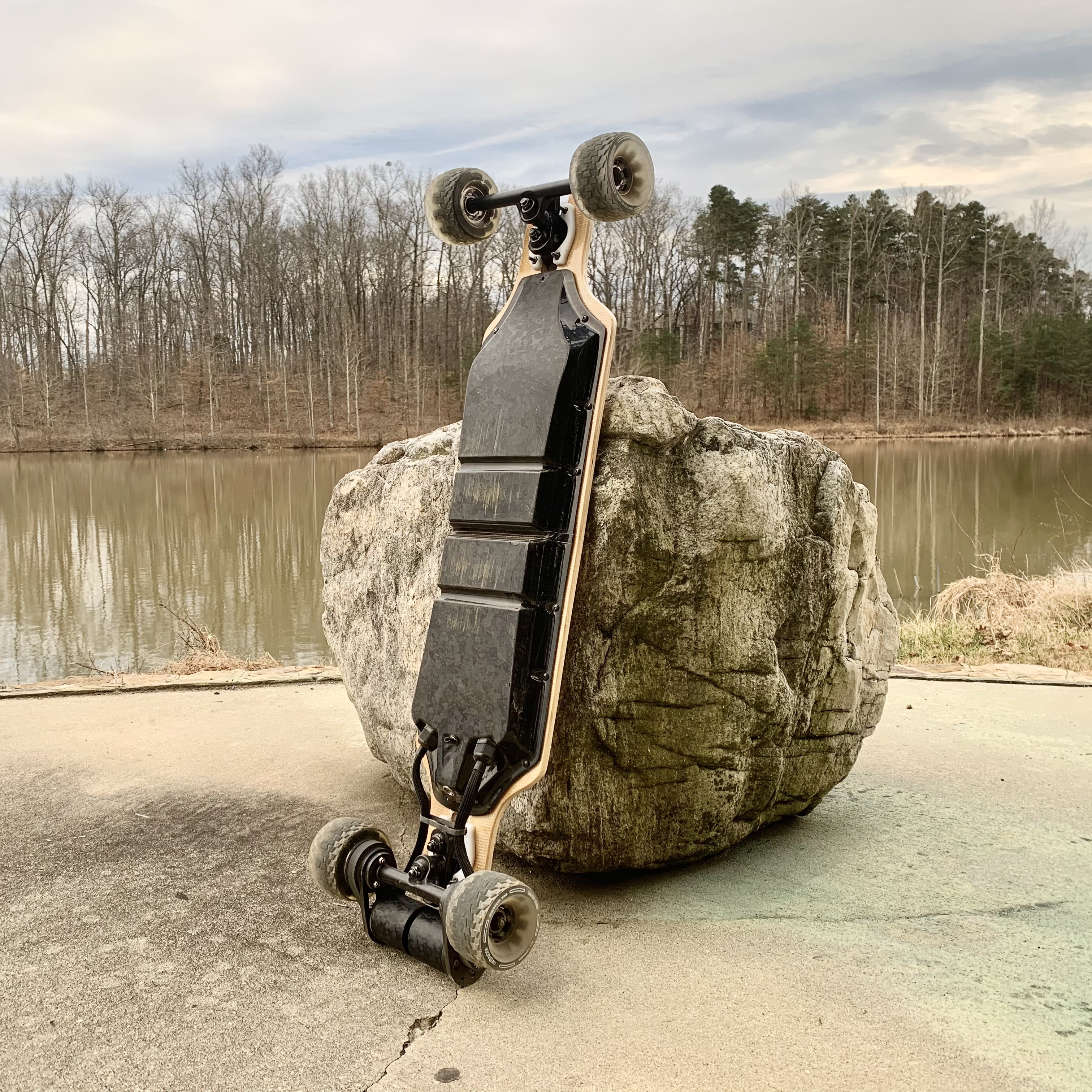
A couple weeks after I completed the build, I decided to make a rear bumper cage to protect the motors from accidental impact or scratches. The frame consists of a CNC routed uhmw plastic frame and standoffs. The bumper cage doubles as mounting for a handle and a belt protector. I wove a paracord that incorporates some hex nuts for a wider distributed grip. I can now easily drag the heavy 25lb electric longboard around like luggage which is much easier than picking the entire thing up and carrying it.
This electric longboard build was by far one of my most complex projects. Along with pushing my design skills to the limit with 3d surfacing, I had to research enough about two unique tools to build them from scratch to fit my needs. I will definitely use the vacuum thermoformer and spot welder again for a future project. The best part is that the fun didn’t stop after the build was complete, I now have a one of a kind high powered electric vehicle that I can ride every day. As I’m writing this a few weeks after I finished the build, I have in fact ridden this board nearly every day for a couple miles and haven’t had any major problems.
Skills Enhanced
- CAD (PTC Creo Parametric)
- FEA (PTC Creo Simulate)
- CAM (Fusion 360)
- Mold Making
- CNC Routing
- Vacuum Thermoforming
- Spot Welding
- Li-ion Battery Pack Design
- Skateboarding