Pick and Place Robotic Arm
As a part of the University of North Carolina at Charlotte mechanical engineering curriculum, all students take part in MEGR 3156, also known as Junior Design. In one semester students have to design, fabricate and program a working 3 degree-of-freedom pick and place robot that autonomously or manually scans a grid and picks up five randomly placed steel balls to deposit on the other side of the robot as fast as possible. As requirements for this project, the pick up and drop off grid dimensions are given as well as maximum power and motor specs. Everything else is for the teams to decide. A weighted score combining autonomous time, manual time, total robot weight and robot cost is calculated.
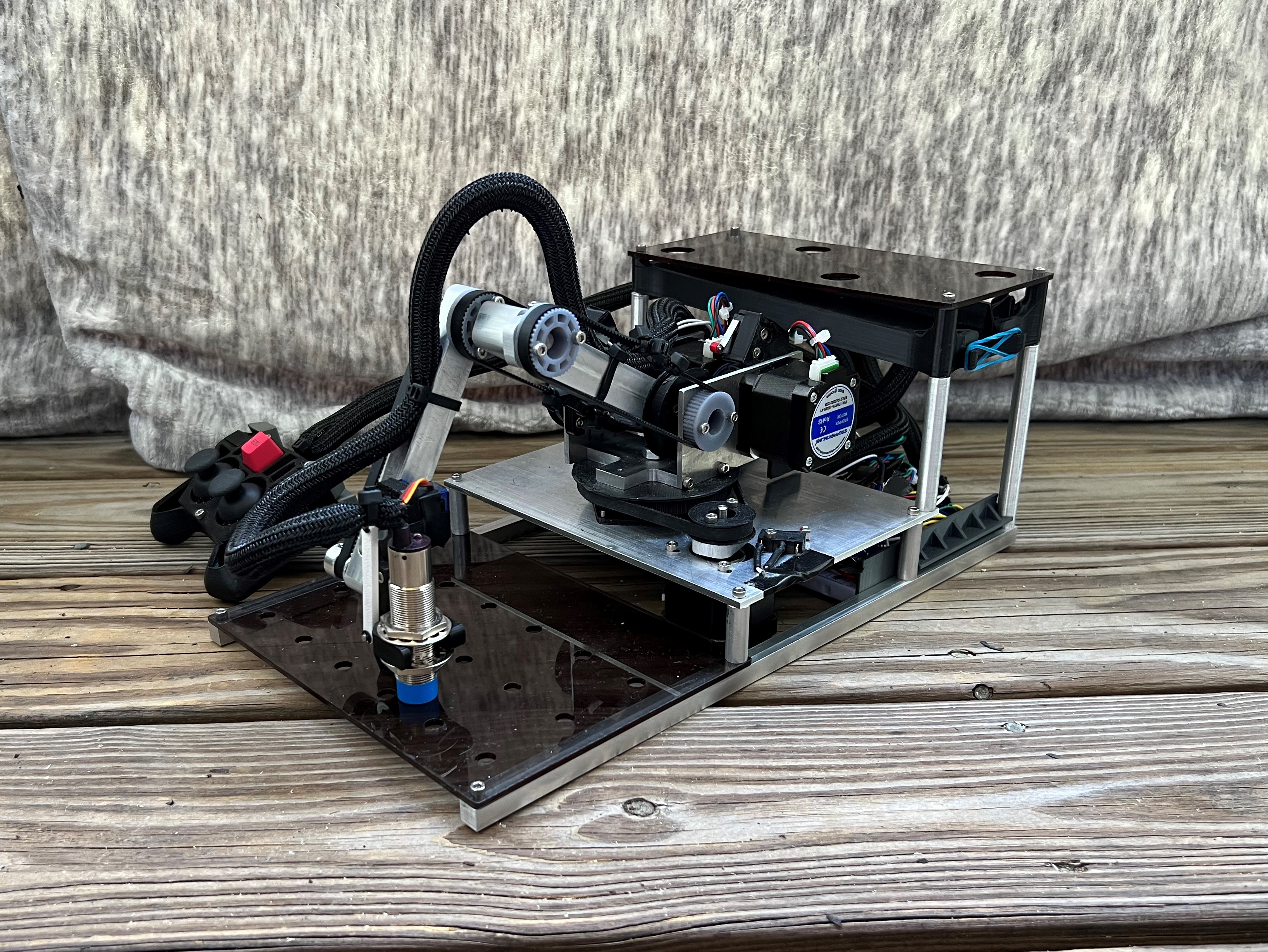
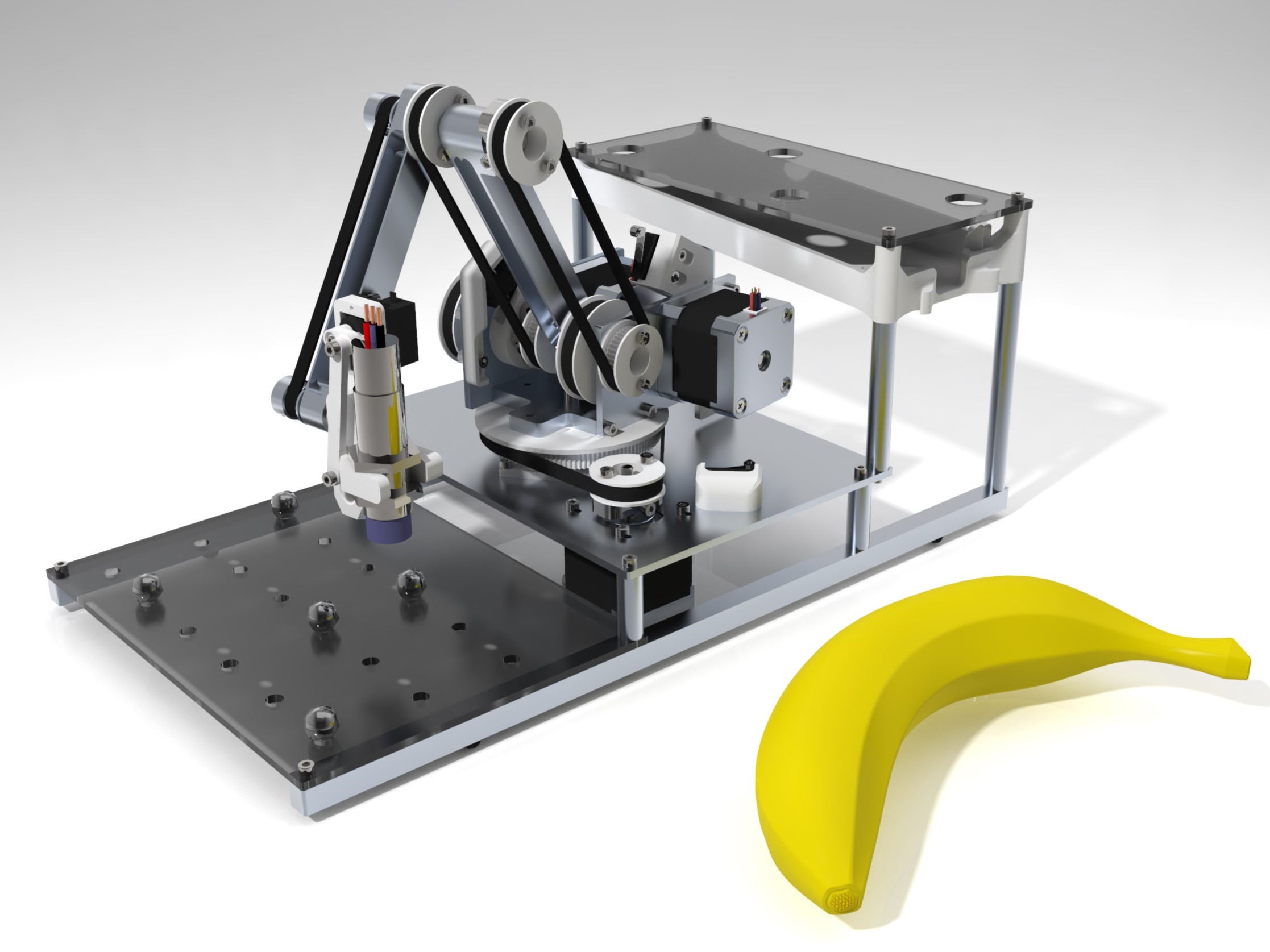
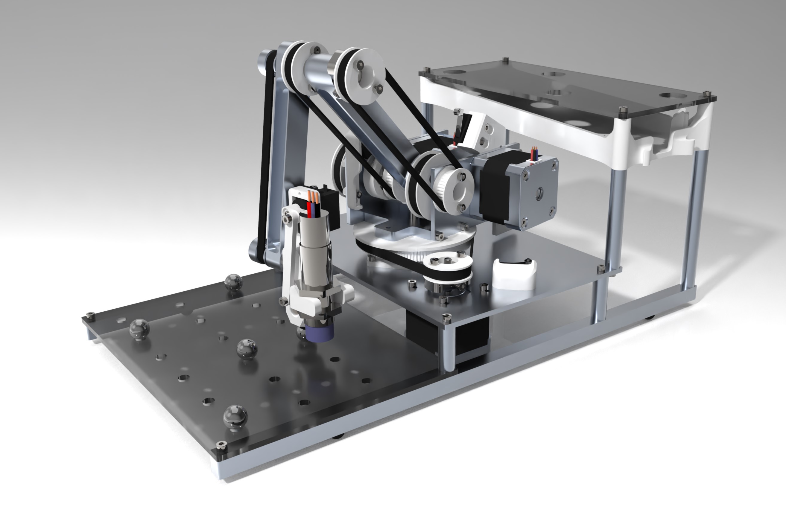
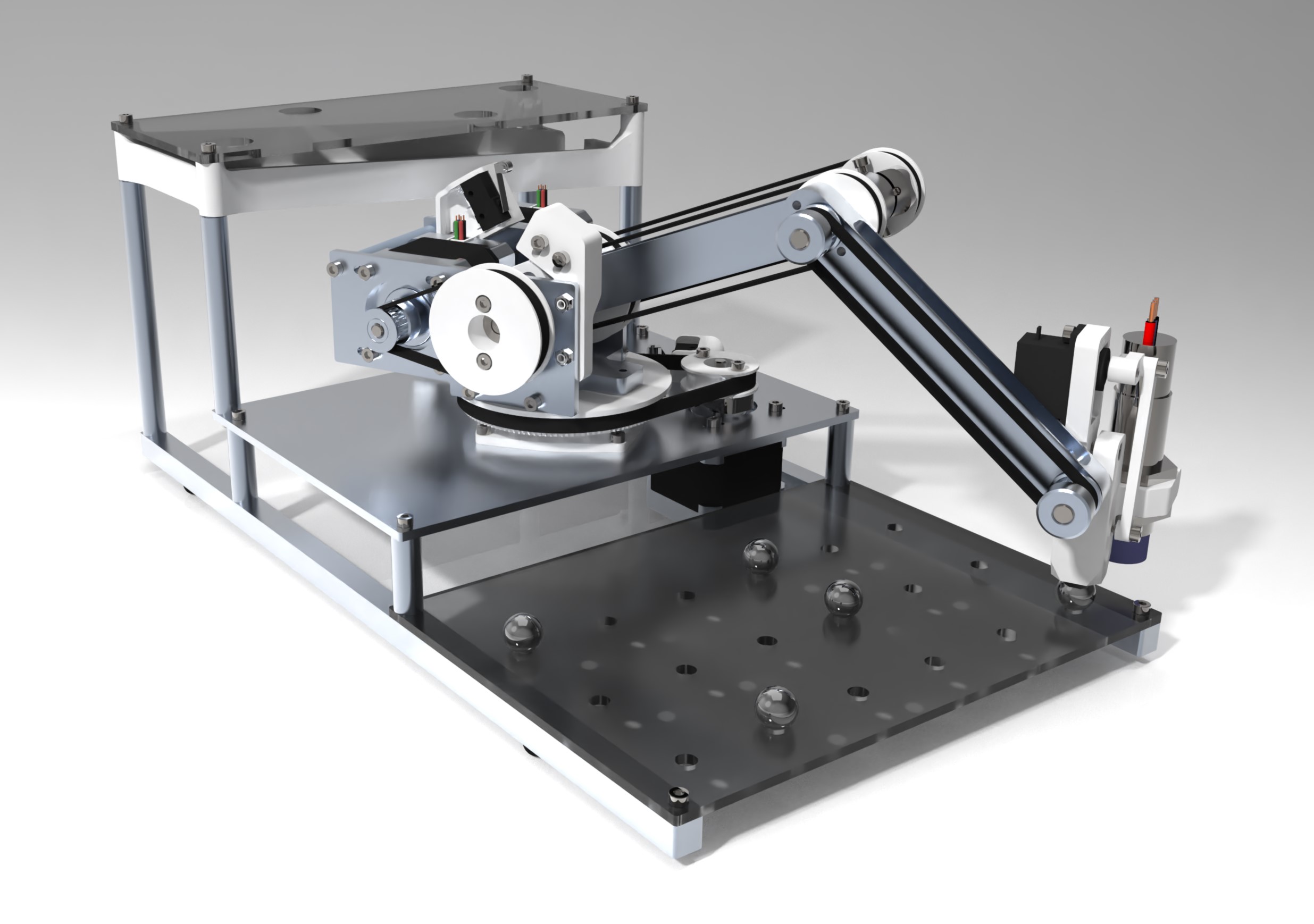
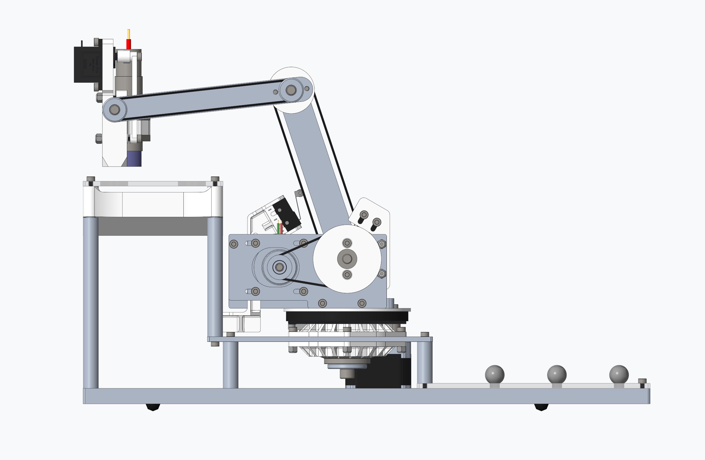
The entire robot can be described as several subassemblies. These subassemblies include the baseplate structure, three rotary axes, and end effector. The entire robot was designed with Creo Parametric and MathCad. Here is a render of the robot’s CAD model with a banana included for size reference.
The baseplate structure is responsible for keeping the ball pick up and drop off grid plates in a fixed position relative to the plate that the robot arm is mounted to. The plate that the robot is mounted to and the floor crossbars were machined on a Bridgeport manual mill out of aluminum. The standoffs were machined on a lathe out of aluminum and the pick up and drop off grid plates were cut on a laser cutter out of acrylic. There is a structure underneath the drop off grid plate to catch the balls after they have been dropped through called the ball catcher. The ball catcher was 3d printed out of pla.
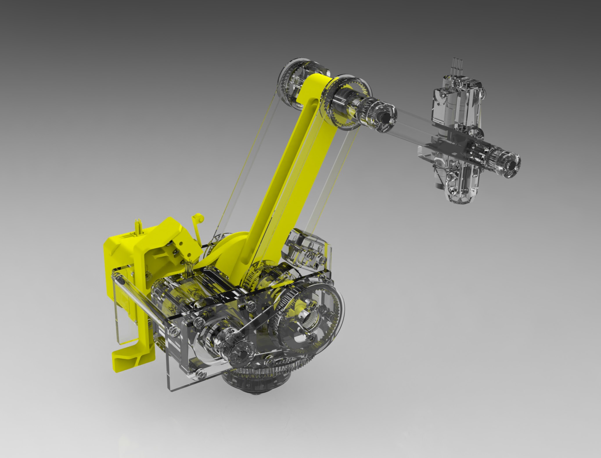
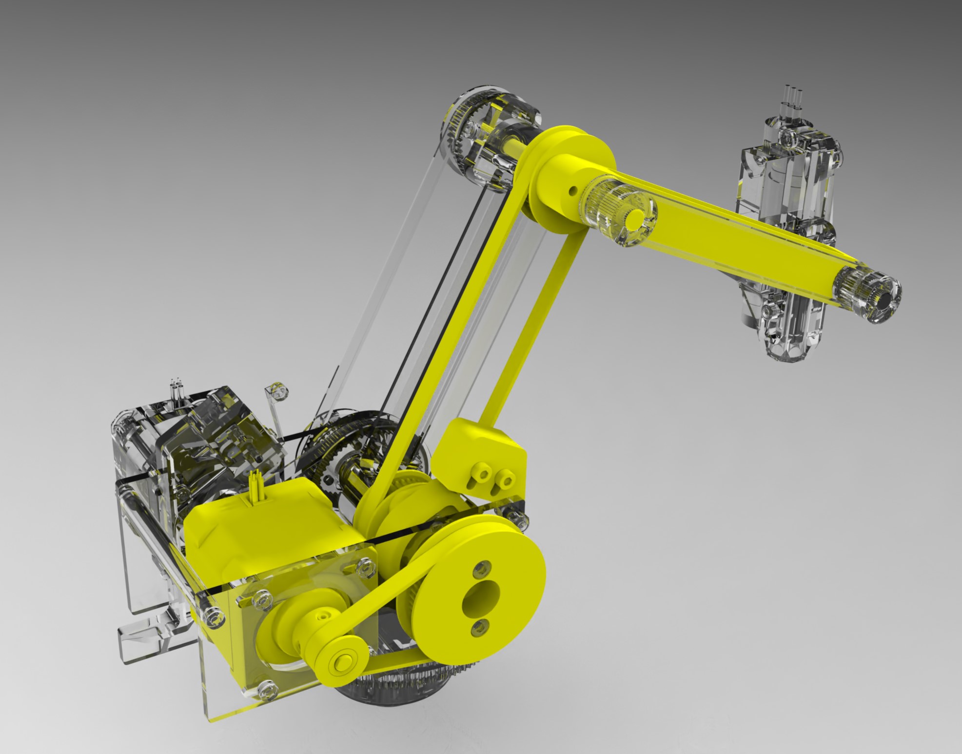
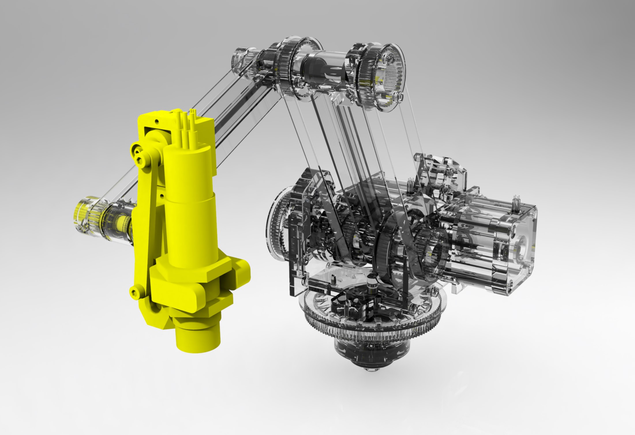
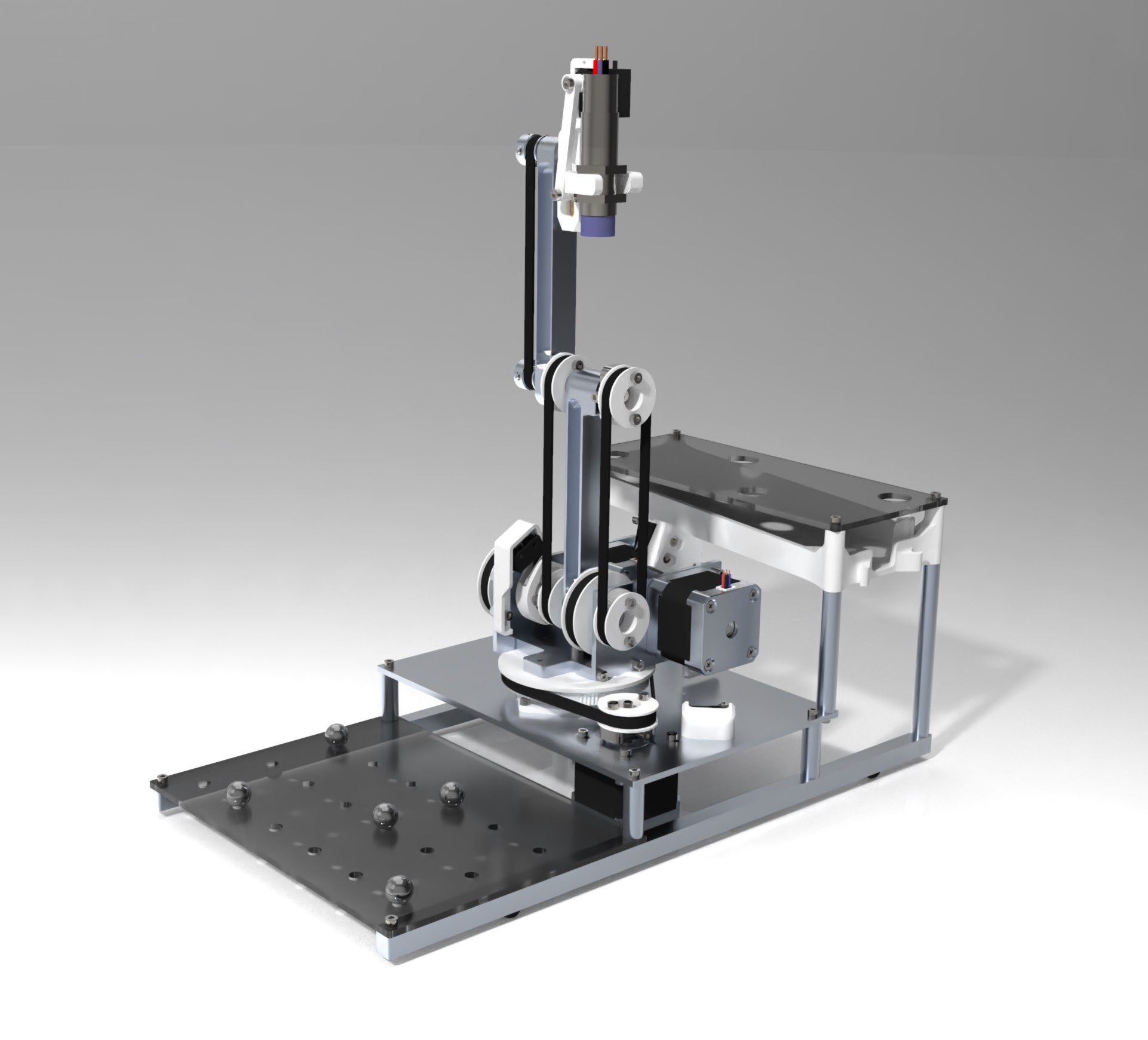
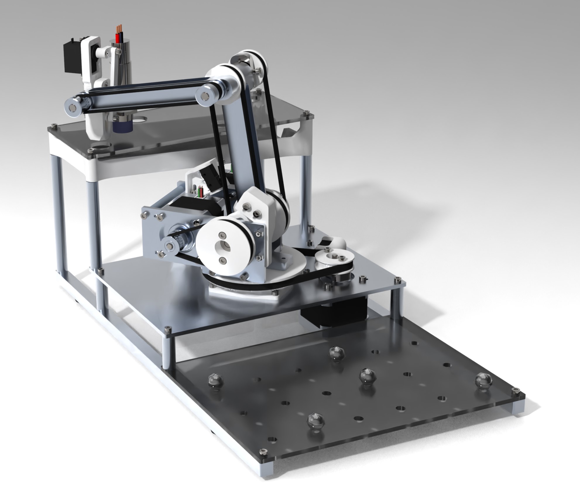
Each of the three rotary axes are highlighted in the images below in order of first to third rotary axis. The three rotary axes were actuated by Nema 17 stepper motors with a 3:1 pulley reduction. Limit switches were placed on each of the rotary axes for homing during the set up procedure.
The end effector had three parts, a magnetic ball gripper, inductive proximity sensor, and stabilization mechanism. A magnet was placed on the end of a linkage activated piston slider to attach and detach to steel balls. The linkage link lengths were optimized to release the ball as quickly as possible with the limited power of a micro-servo. On the end effector right next to the magnetic piston slider is an inductive proximity sensor responsible for detecting steel balls on the pick up grid.
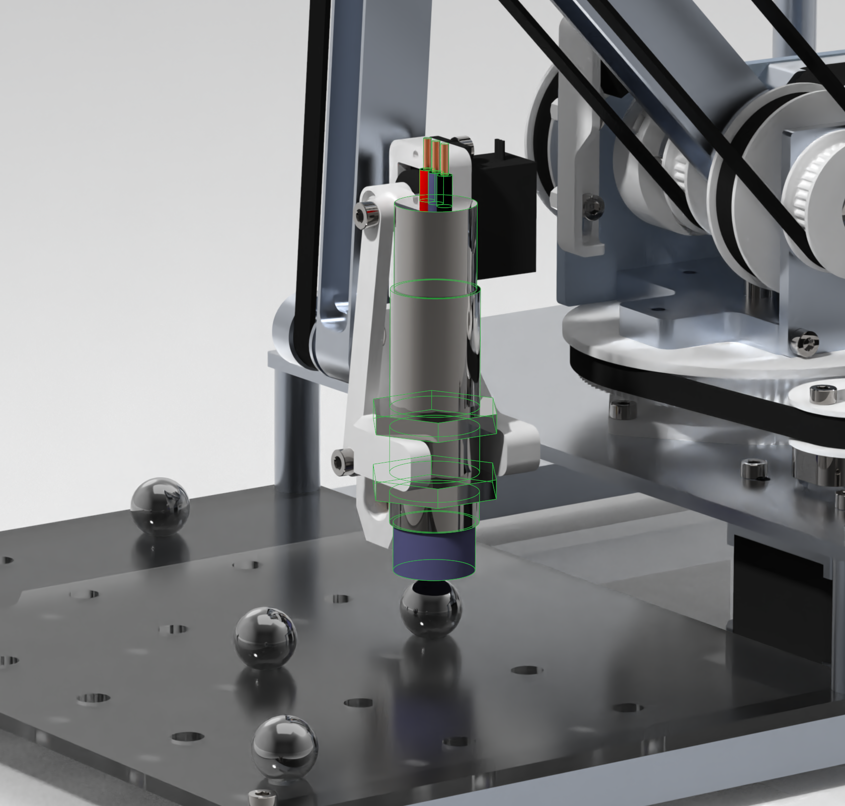
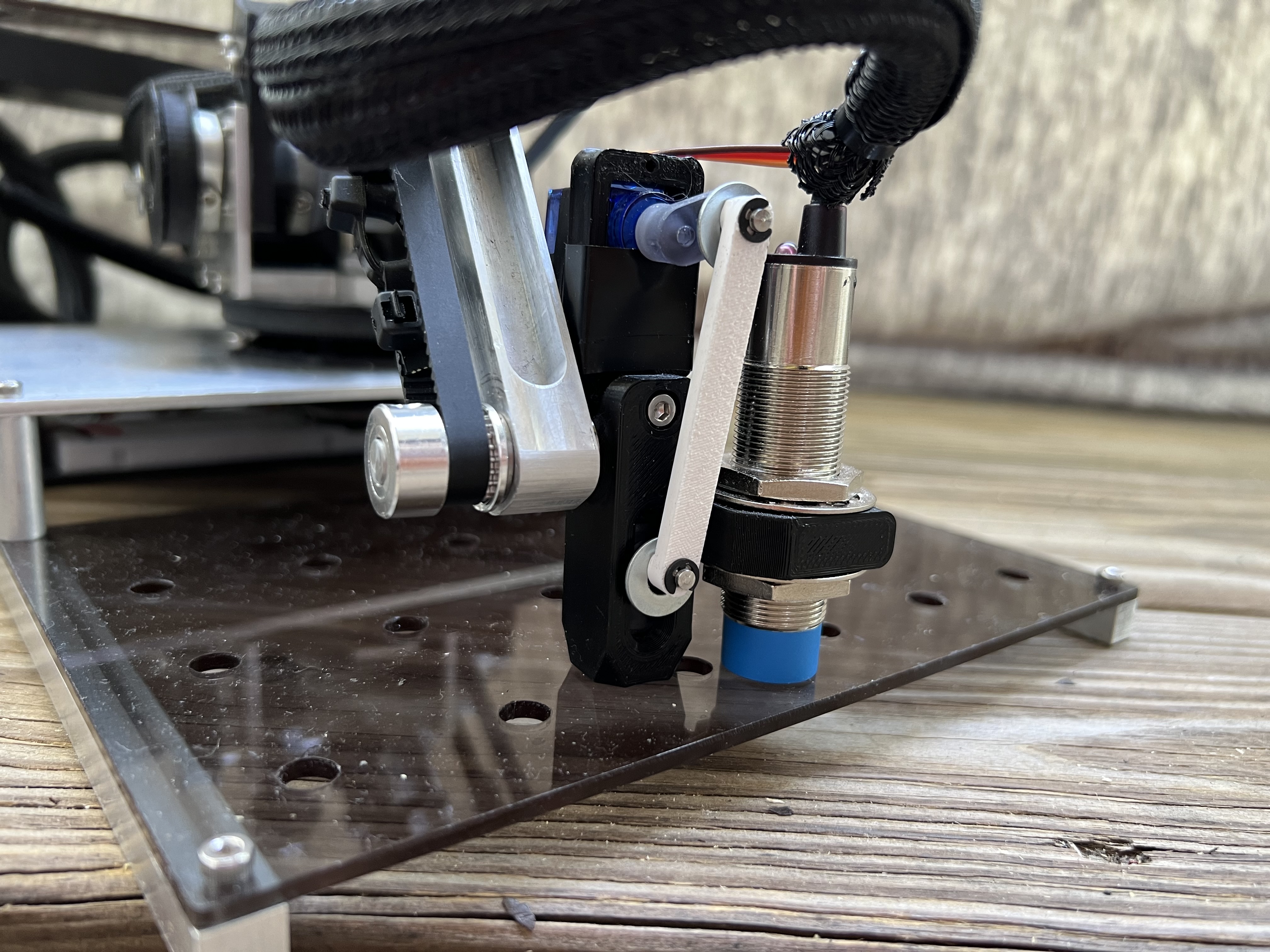
The end effector is stabilized by a pair of belts and pulleys through to the frame of the first rotary axis. The end effector stabilizer keeps the end effector perpendicular to the grid plates independent of the second and third rotary axis angle.
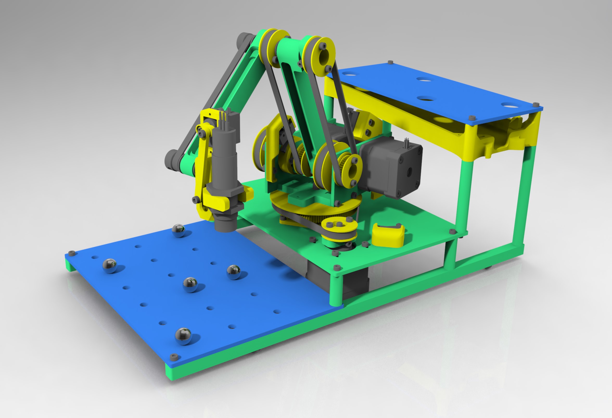
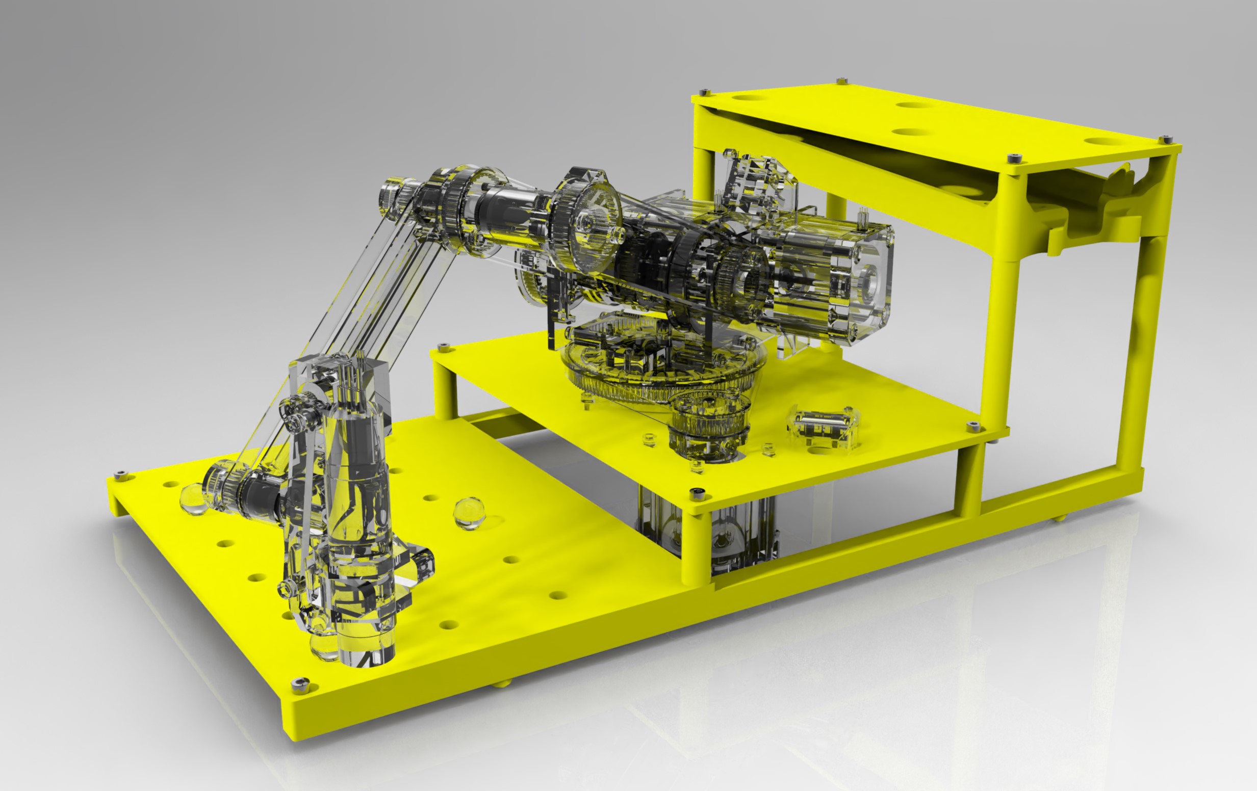
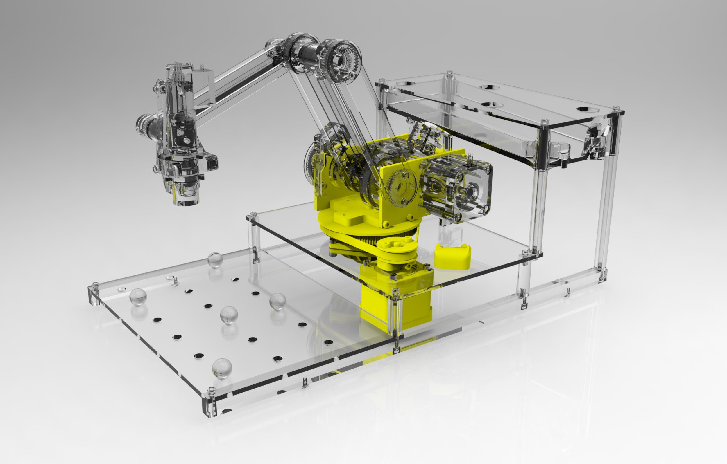
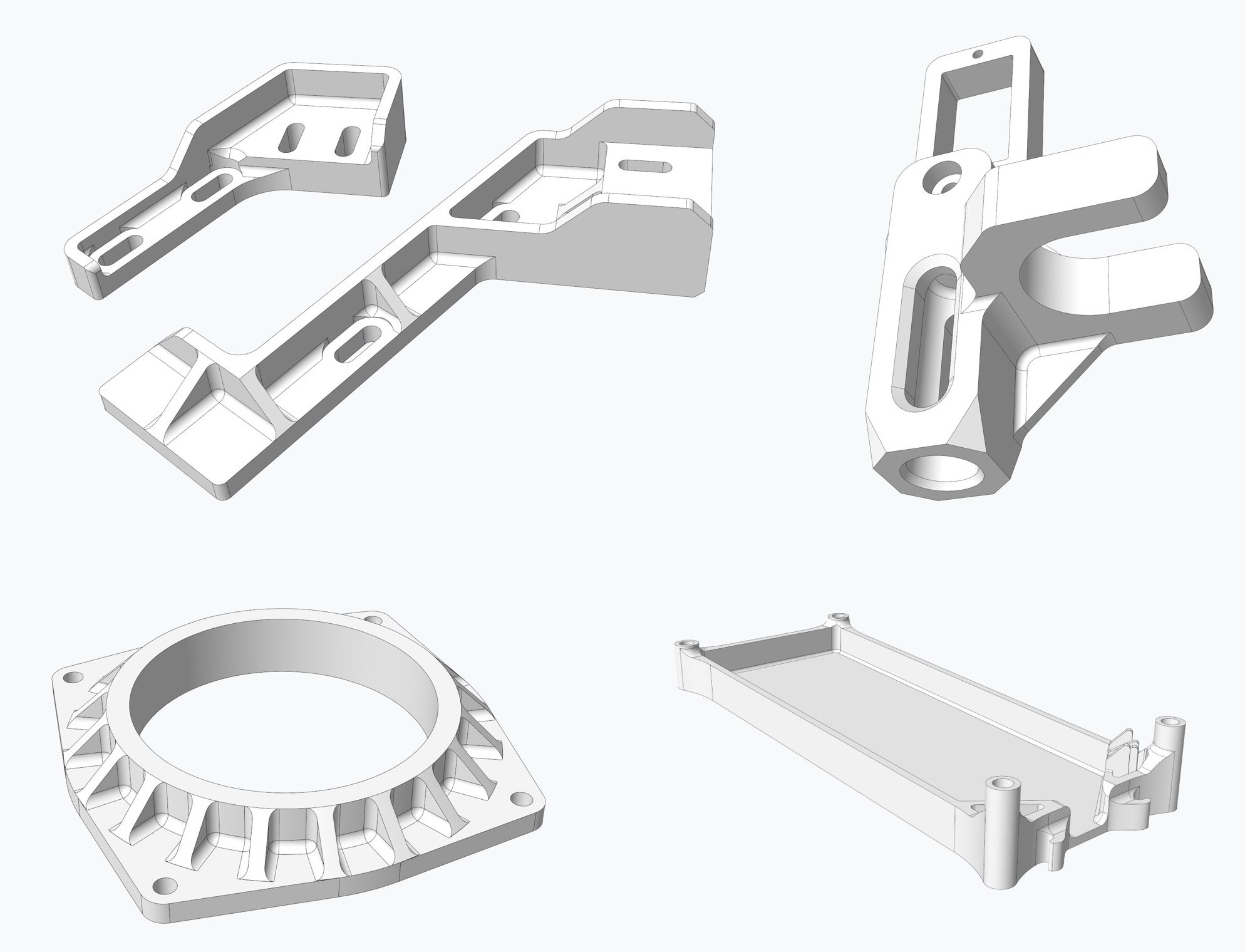
The image above shows the different manufacturing methods used to create this robot. All of the parts shown in green were first saw cut down from stock material size then machined either with a manual mill or lathe. The parts shown in blue were laser cut out of acrylic sheets. The yellow parts were 3D printed. Some of the 3D printed parts that needed higher resolution were printed on my SLA resin 3D printer. The rest of the parts were printed with a traditional FDM 3D printer. Some examples of the 3D printed parts on this robot are shown in the image below.
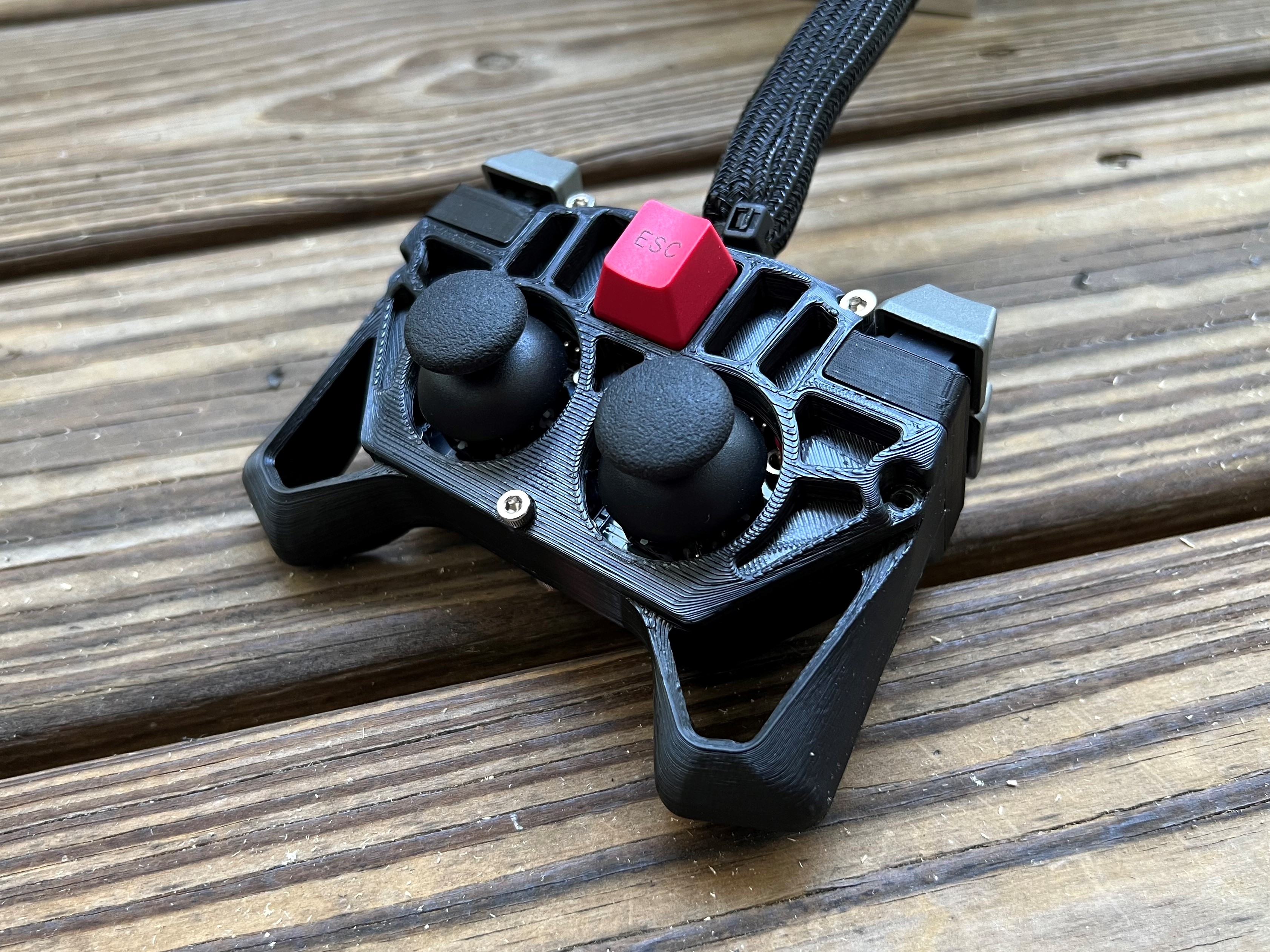
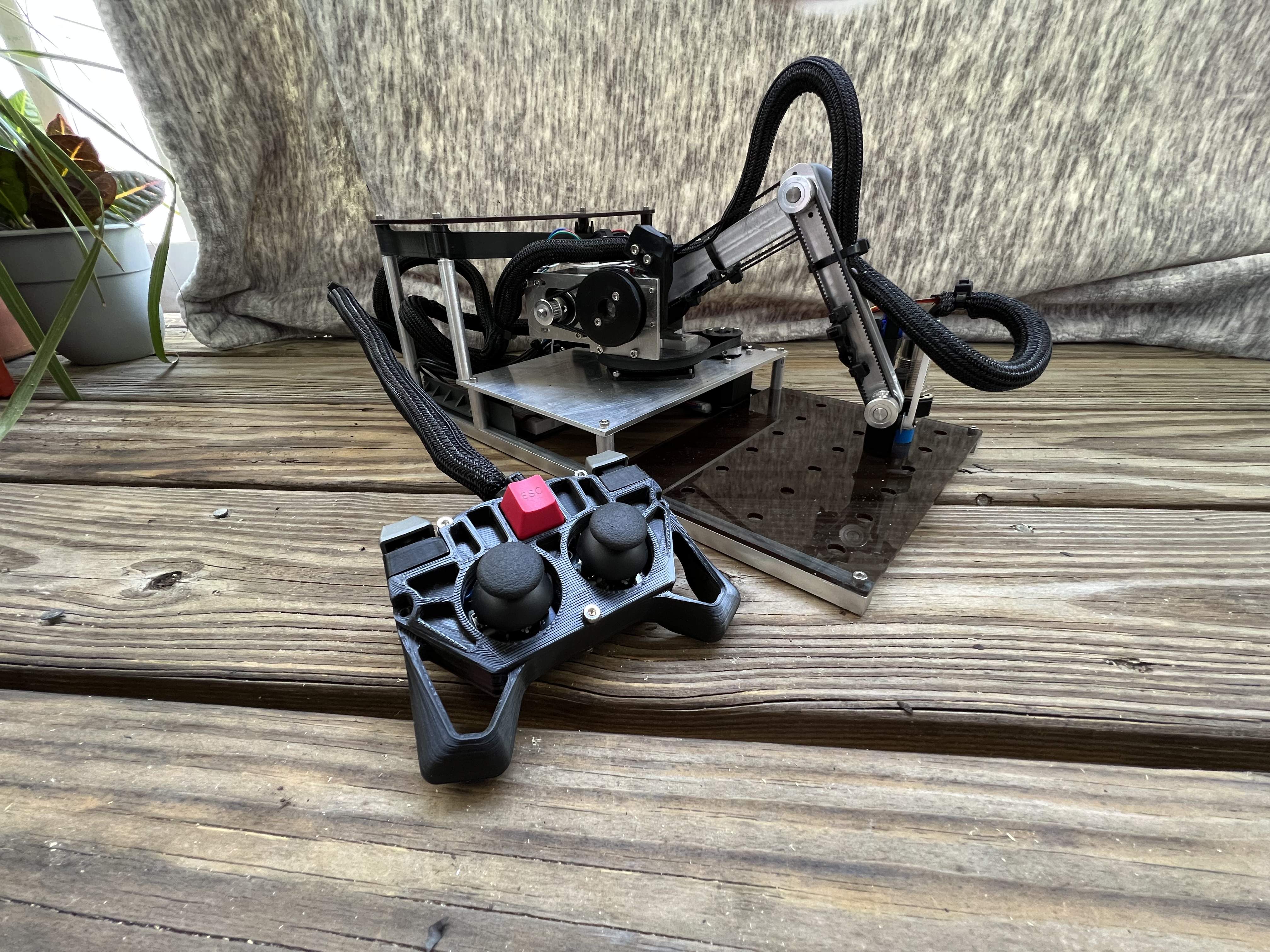
A handheld controller was designed and 3D printed for manual control of the robot by a user. This was a required part of the assignment for a theoretical scenario where the autonomous program does not work. Two joysticks were used to control the robot’s rotary axis. Five mechanical keyboard switches were mounted to the handheld controller for other functions.
The most interesting thing about this robot is that the end effector moves up and over the robot to move between the pick up and drop off positions, as opposed to around the robot. This was a design decision early on that would significantly complicate the end effector stabilization, but make faster cycle times a possibility. The reasoning behind moving the end effector up and over verses around the robot is that less movement is required for the first rotary axis. Most of the movement up and over is done by the second and third rotary axis. Rotary axis angular acceleration is directly dependent on the torque generated by the stepper motor before skipping steps. In addition to gravity forces, moving less mass means the rotary axis can accelerate faster. The arm links attached to the second and third rotary axis are very light weight machined aluminum bars. The second and third rotary axis can swing significantly faster than the first rotary axis. Whenever the first rotary axis rotates, it must also move the weight of the second and third rotary axes’ stepper motors. Having the option to move the first rotary axis at most 90 degrees versus at most 270 degrees per cycle was an obvious choice.
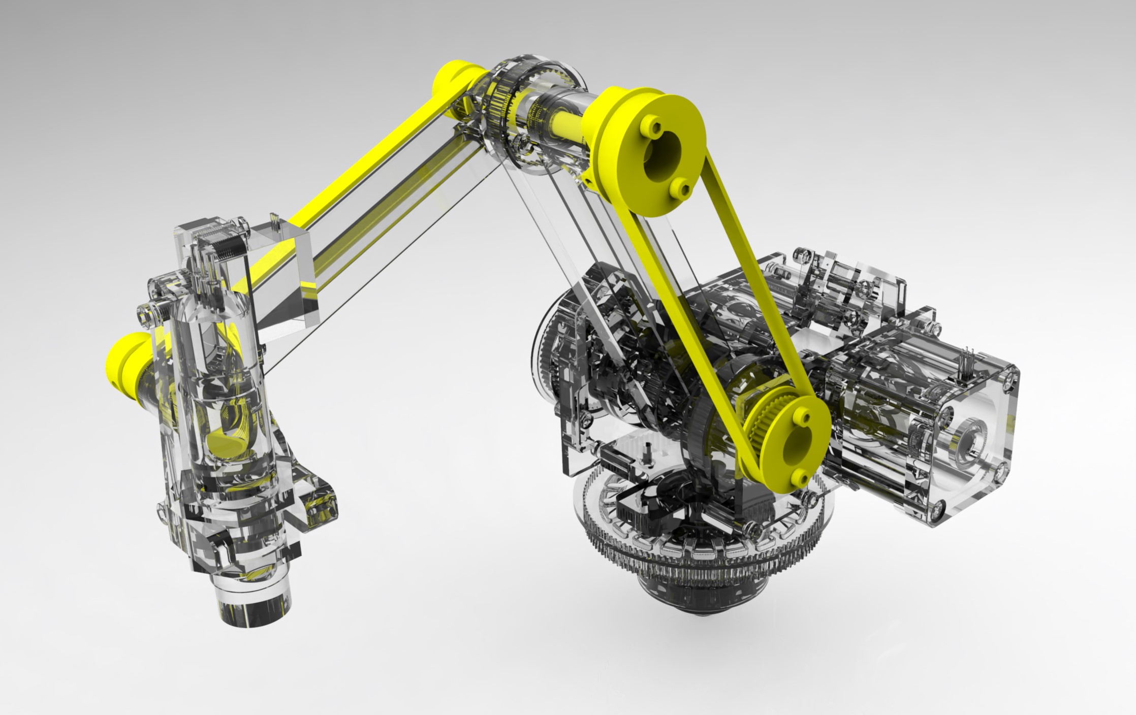
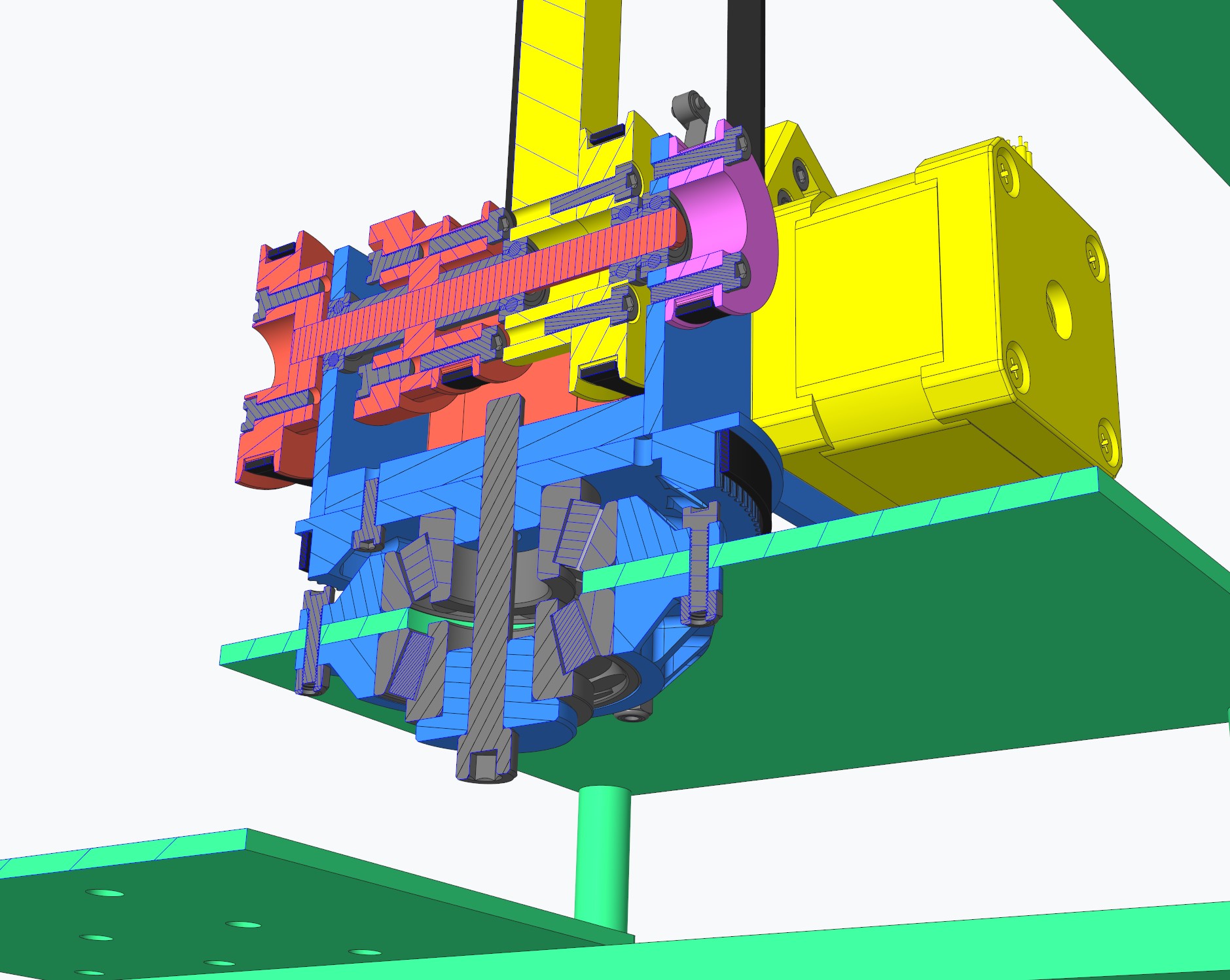
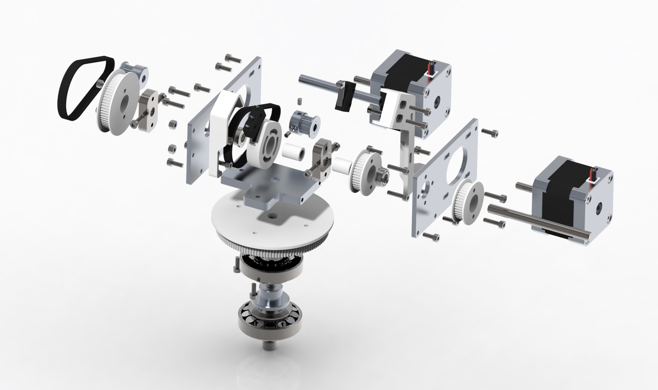
The most complicated part of the mechanical design for this robot is the junction between the first and second rotary axis. This junction also included an intermediate co-axially mounted shaft to actuate the third rotary axis, another co-axially mounted pulley as the reference angle mount for the end effector stabilization mechanism, the stepper motor mounts for the second and third rotary axis, and limit switch mounts for homing the second and third rotary axes. Shown below are an exploded view of the assembly and a colored cross section. In the cross section image, green is the base frame, blue is the first rotary axis, yellow is the second rotary axis, red is the intermediate third rotary axis shaft assembly and magenta is the gripper stabilization reference pulley.
Getting the robot to work for the first time was very straightforward and easy. I created a diagnostic program first to make sure all stepper motors, servo and sensors worked independently and everything was wired correctly. I burnt out a stepper motor driver on the first try, because I accidentally swapped two wires. A smarter me would have looked at the documentation instead of trying to read the tiny text on the circuit board. After getting all of the stepper motors and servo to move correctly and getting readings from all the sensors, I was able to incrementally add parts of the program until the entire program was implemented. A single xyz-coordinate system was used for all of the grid positions. I created inverse kinematic functions to generate rotary axis angles from cartesian coordinates. The robot scanned all of the positions on the pick up grid for 5 steel balls. Then the robot would pick up the balls one by one and drop them into the drop off grid. At this point the robot used fixed acceleration values for each stepper motor and a simple pick up and drop off sequence. It could scan the entire grid and pick up and drop off all 5 balls in about 20 seconds. This was the easy part. I knew I could make the robot go much faster.
The first thing that I did was create a function to store the locations where the balls were detected. Being able to store locations means that the robot can scan the entire grid without stopping, then only picking up balls once all locations have been scanned. Scanning everything without stopping intermittently to pick up and drop off a ball saved some time, but something else could be done with the saved ball location data. The optimal ball pick up and drop off order could be found instead of simply using the order in which the balls were scanned. Interestingly, the drop off location with the closest linear distance to the pick up location did not result in the fastest possible cycle. The sequence in which balls were picked up and where they are dropped off are dependent on where they are located. Implementing location dependent cycle sequencing saves between 2 to 6 seconds depending on the ball locations.
The most testing was done creating a function to optimize acceleration values for each stepper motor for every possible move that the robot can make. Depending on the pick up and drop off position that the robot is trying to move between, all three stepper motors have different optimal acceleration values. In simple terms, the main limitation of stepper motors is that if they are told to move to a position, but there is too much load, the stepper motor will skip steps and lose position. This applies to accelerating a rotary axis. The third rotary axis can theoretically accelerate faster than the second and first rotary axis since it has to move less mass. In addition to accelerating the mass around a rotary axis, the constant downwards force of gravity significantly affects the maximum acceleration possible for each axis. Gravity force only applies to the second and third rotary axis. The first rotary axis only has to accelerate mass. Taking into account that each pick up and drop off location positions each rotary axis at a different angle, it is easy to see why a generalized function to calculate acceleration for each stepper motor is desirable. Even going from the same pick up to drop off locations will have different acceleration values than going from the same drop off to pick up locations, because the robot will be carrying the extra mass of the steel ball.
A function was created to calculate the optimal acceleration values for each stepper motor for each possible move. This function was split up into two main parts. Calculating acceleration and synchronizing movement. Since every single mechanical component on the robot was modeled in CAD, mass for each component could be easily calculated and included in an equation to calculate acceleration. This equation outputs three acceleration values for each rotary axis from the cartesian start and end positions. Inverse kinematic equations were included in this equation to calculate the angles of the second and third rotary axis. The angles are needed to include gravity force in the equation. An assumption made is that the acceleration and deceleration values are the same. Using different acceleration and deceleration values would require further testing and would significantly complicate the synchronization of all the rotary axes.
After acceleration values for each rotary axis were found, a function was used to synchronize all of the movements. Without synchronization, a rotary axis that has less to travel or has higher acceleration than another axis will complete its movement before the others. This results in excessively jerky movement that may cause another rotary axis to skip steps. To synchronize all of the axis, the axis that will take the longest amount of time to complete its movement was used as a reference. Since the top usable speed of the stepper motor is never reached, a triangular motion profile was used. This means that the stepper motor will accelerate until it reaches half of the target angle then immediately start decelerating. I had first tried implementing a trapezoidal motion profile on the two faster axes and a triangular motion profile on the slower axis to synchronize movement, but it was not as smooth as I would have wanted. The trapezoidal motion profile used the fastest acceleration values for that particular move and scaled top speed before decelerating. Instead of using trapezoidal motion profiles, triangular motion profiles were used on all axes. The acceleration values on the faster two axes were scaled down to match the timing on the slower reference axis. This resulted in the smoothest movement with the least chance of skipping stepper motor steps. Finding optimal acceleration values and synchronizing each axis movements saves around 5 additional seconds.
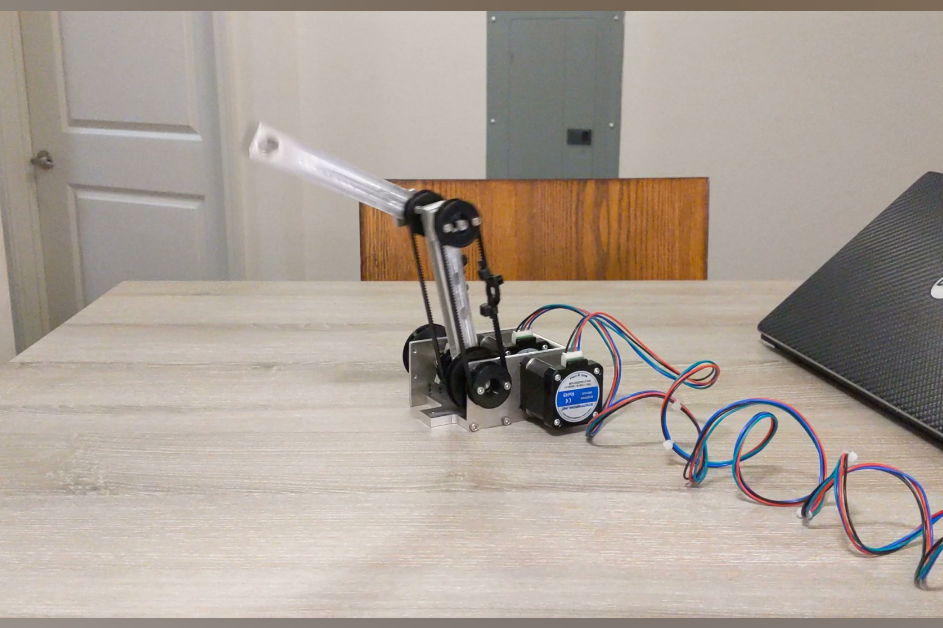
After all of the code optimizations, the robot can scan a grid of 18 locations and pick up and drop off 5 balls in under 10 seconds. I’ve been told by the professor for this class that this is the fastest robot anyone has made for this project since they first introduced it several years ago. I hope to hold the record for at least a couple more semesters. My robot was put on display in the lobby of Duke Centennial Hall on UNCC’s engineering campus.
Skills Enhanced
- CAD (PTC Creo Parametric)
- Machining (Mill and Lathe)
- Programming (Arduino)